NOTE: Equip yourself with antistatic protection and a replacement small
CAUTION: To prevent degraded performance, do not twist, fold, pinch, or step on fibre optic cables. Do not bend the fibre optic cables tighter than a 5 cm (2 inch) radius.
1.If possible, use the MD Storage Manager to create, save, and print a new storage array profile.
2.If the Recovery Guru directed you to replace a failed RAID controller module, go to step 3, else run the Recovery Guru to identify the failed component.
3.Unpack the new SFP+ transceiver.
![]() NOTE: Ensure that the SFP+ transceiver is replaced by the same type.
NOTE: Ensure that the SFP+ transceiver is replaced by the same type.
NOTE: Set the new SFP+ transceiver on a dry, level surface near the RAID controller module, the RAID controller module enclosure, or the expansion enclosure.
![]() NOTE: Save all the packing materials in case you need to return the SFP+ transceiver.
NOTE: Save all the packing materials in case you need to return the SFP+ transceiver.
4.To locate a failed SFP+ transceiver, view the FC IN (host channel) speed LEDs on the front of the RAID controller modules. If an SFP+ transceiver has failed, both FC IN speed LEDs for a particular port are off.
•If both FC IN speed LEDs are off for a particular port with a known good cable, the SFP+ transceiver must be replaced. Go to step 6.
•If at least one FC IN speed LED is on for a particular port, the SFP+ transceiver is functional. The FC IN speed LEDs indicate a channel speed of 4Gbps, 8Gbps, or 16Gbps. Ensure that the speed indicated by the LEDs is what is expected.
WARNING: Data processing environments can contain equipment transmitting on system links with laser modules that operate at greater than Class 1 power levels. Never look into the end of an optical fiber cable or open receptacle.
CAUTION: To prevent degraded performance, do not twist, fold, pinch, or step on fiber optic cables. Do not bend the fiber optic cables tighter than a 5 cm (2 inch) radius.
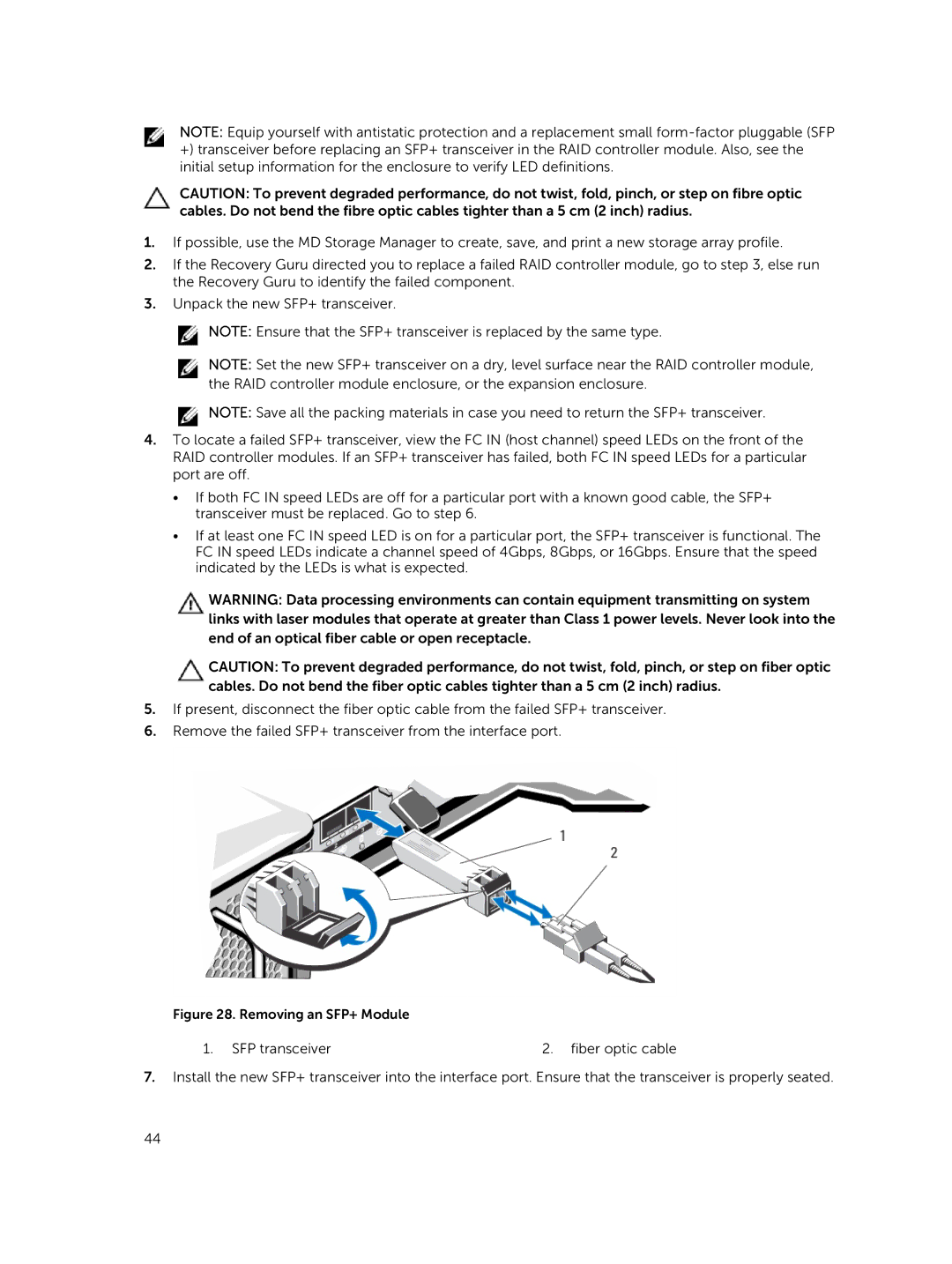
5.If present, disconnect the fiber optic cable from the failed SFP+ transceiver.
6.Remove the failed SFP+ transceiver from the interface port.
Figure 28. Removing an SFP+ Module
1. SFP transceiver | 2. fiber optic cable |
7.Install the new SFP+ transceiver into the interface port. Ensure that the transceiver is properly seated.
44