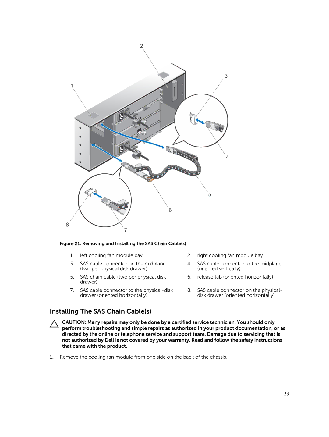
Figure 21. Removing and Installing the SAS Chain Cable(s)
1.left cooling fan module bay
3.SAS cable connector on the midplane (two per physical disk drawer)
5.SAS chain cable (two per physical disk drawer)
7.SAS cable connector to the
2.right cooling fan module bay
4.SAS cable connector to the midplane (oriented vertically)
6.release tab (oriented horizontally)
8.SAS cable connector on the physical- disk drawer (oriented horizontally)
Installing The SAS Chain Cable(s)
CAUTION: Many repairs may only be done by a certified service technician. You should only perform troubleshooting and simple repairs as authorized in your product documentation, or as directed by the online or telephone service and support team. Damage due to servicing that is not authorized by Dell is not covered by your warranty. Read and follow the safety instructions that came with the product.
1.Remove the cooling fan module from one side on the back of the chassis.
33