Item | Indicator, Button, or | Icon | Description |
| Connector |
|
|
|
|
|
|
3 | Node status indicators |
| Provide information about the status of the four |
|
|
| nodes in the sled. |
4 | USB select button |
| Allows you to assign the USB port to a particular |
|
|
| node in the sled. |
5 | USB connector |
| Allows a USB device to be connected to the system. |
6 | Sled handle |
| Used to slide the sled out of the enclosure. |
Hard-drive/SSD indicator patterns
The
NOTE: The sled must have a hard drive/SSD or a
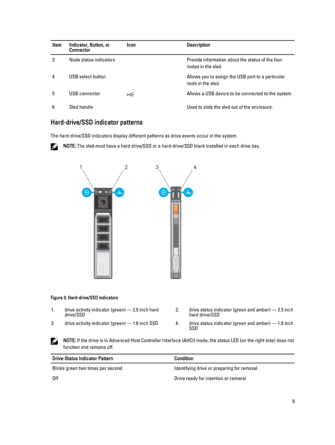
Figure 3. |
|
| |
1. | drive activity indicator (green) — 2.5 inch hard | 2. | drive status indicator (green and amber) — 2.5 inch |
| drive/SSD |
| hard drive/SSD |
3. | drive activity indicator (green) — 1.8 inch SSD | 4. | drive status indicator (green and amber) — 1.8 inch |
|
|
| SSD |
NOTE: If the drive is in Advanced Host Controller Interface (AHCI) mode, the status LED (on the right side) does not function and remains off.
| Condition |
|
|
Blinks green two times per second | Identifying drive or preparing for removal |
Off | Drive ready for insertion or removal |
9