Remove Jumper if |
Installed |
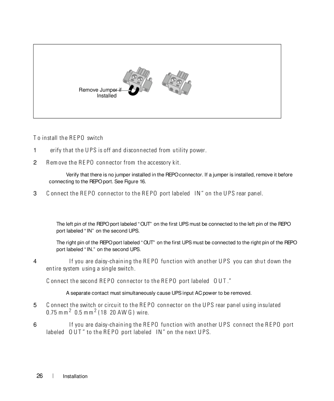
Figure 16. REPO Connector
To install the REPO switch:
1Verify that the UPS is off and disconnected from utility power.
2Remove the REPO connector from the accessory kit.
NOTE: Verify that there is no jumper installed in the REPO connector. If a jumper is installed, remove it before connecting to the REPO port. See Figure 16.
3Connect the REPO connector to the REPO port labeled “IN” on the UPS rear panel.
CAUTION: If you are
SThe left pin of the REPO port labeled “OUT” on the first UPS must be connected to the left pin of the REPO port labeled “IN” on the second UPS.
SThe right pin of the REPO port labeled “OUT” on the first UPS must be connected to the right pin of the REPO port labeled “IN.” on the second UPS.
4Optional. If you are
Connect the second REPO connector to the REPO port labeled “OUT.”
NOTE: A separate contact must simultaneously cause UPS input AC power to be removed.
5Connect the switch or circuit to the REPO connector on the UPS rear panel using insulated 0.75
6Optional. If you are