SECTION 2.4
Logic Interface and Connection
Optically Isolated Logic Inputs
The Microstepping MForce PowerDrive has three optically isolated logic inputs which are located on connector P1. These inputs are isolated to minimize or eliminate electrical noise coupled onto the drive control signals. Each input is internally
1] Step Clock (SCLK)/Quadrature (CH A)/Clock UP
2] Direction (DIR)/Quadrature (CH B)/ Clock DOWN
3] Enable (EN)
Of these inputs only step clock and direction are required to operate the Microstepping MForce PowerDrive.
Isolated Logic Input Pins and Connections
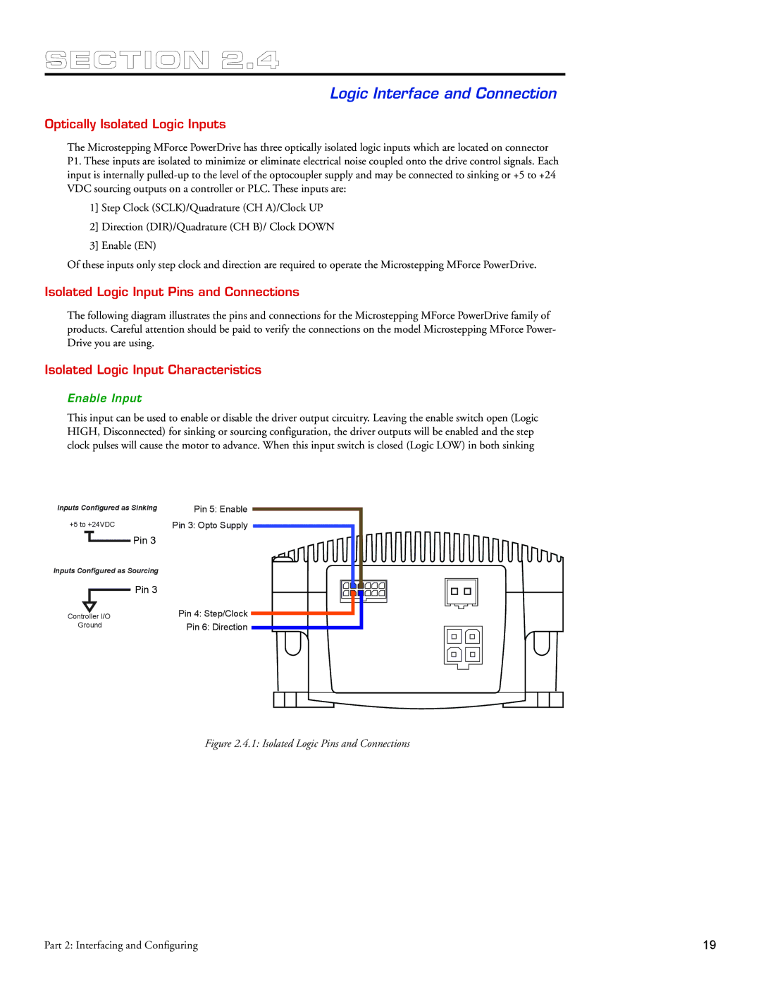
The following diagram illustrates the pins and connections for the Microstepping MForce PowerDrive family of products. Careful attention should be paid to verify the connections on the model Microstepping MForce Power- Drive you are using.
Isolated Logic Input Characteristics
Enable Input
This input can be used to enable or disable the driver output circuitry. Leaving the enable switch open (Logic HIGH, Disconnected) for sinking or sourcing configuration, the driver outputs will be enabled and the step clock pulses will cause the motor to advance. When this input switch is closed (Logic LOW) in both sinking
Inputs Configured as Sinking
+5 to +24VDC
Pin 3
Inputs Configured as Sourcing
Pin 3
Controller I/O
Ground
Pin 5: Enable Pin 3: Opto Supply
Pin 4: Step/Clock Pin 6: Direction
Figure 2.4.1: Isolated Logic Pins and Connections
Part 2: Interfacing and Configuring | 19 |