GETTING STARTED
Microstepping MForce PowerDrive
Before You Begin
The Getting Started Section is designed to help quickly connect and begin using your Microstepping MForce PowerDrive. The following examples will help you get a motor turning for the first time and introduce you to the basic settings of the drive.
Tools and Equipment Required
Microstepping MForce PowerDrive Unit (MFM)
A NEMA 23 or 34 Size Stepping Motor
Control Device for Step/Direction
+5 to +24 VDC Optocoupler Supply (if using sinking output type)
An Unregulated +12 to +48VDC Power Supply
Basic Tools: Wire Cutters / Strippers / Screwdriver
Wire for Power Supply (18 AWG) and Motor (16 AWG)
22 AWG Wire for Logic Connections
WARNING! The MForce has components which are sensitive to Electrostatic Discharge
(ESD). All handling should be done at an ESD protected workstation.
WARNING! Hazardous voltage levels may be present if using an open frame power supply to
power your MForce product.
WARNING! Ensure that the power supply output voltage does not exceed the maximum input
voltage of the MForce product that you are using!
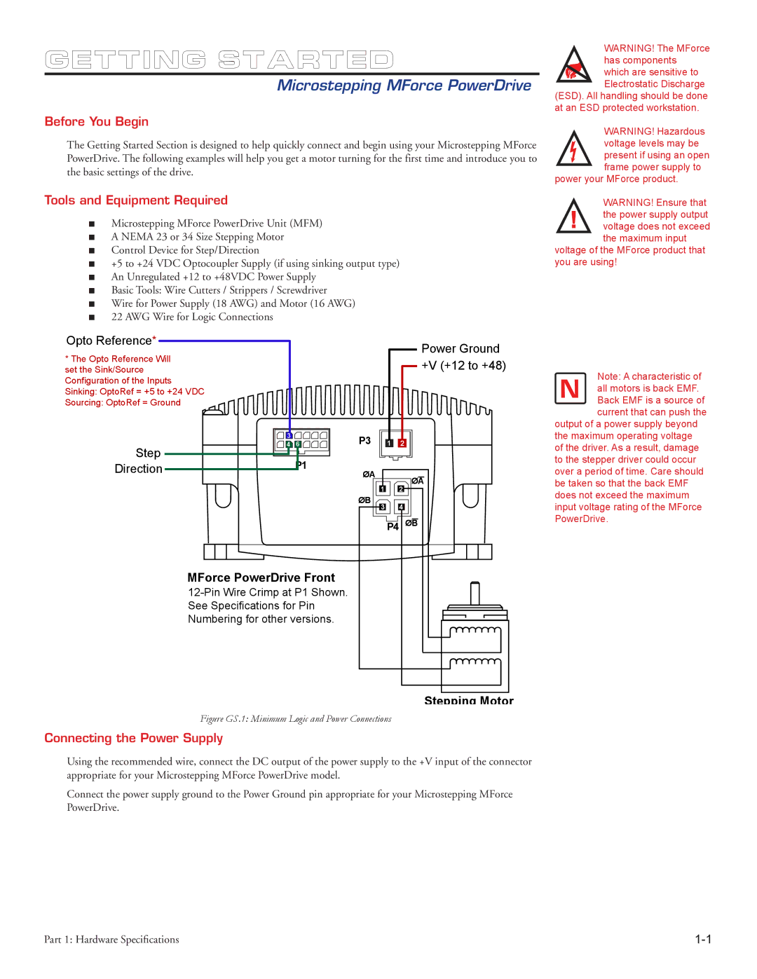
Opto Reference* | Power Ground | |
* The Opto Reference Will | ||
+V (+12 to +48) | ||
set the Sink/Source | ||
Configuration of the Inputs |
| |
Sinking: OptoRef = +5 to +24 VDC |
| |
Sourcing: OptoRef = Ground |
|
| 3 | 6 | P3 |
| 1 | 2 |
Step | 4 |
| ||||
| P1 |
|
|
|
| |
Direction |
| ØA |
|
| ØA | |
|
|
|
|
| ||
|
|
|
| 1 |
| |
|
|
|
|
| 2 | |
|
|
| ØB | 3 |
| 4 |
|
|
|
|
| P4 ØB | |
MForce PowerDrive Front
Note: A characteristic of all motors is back EMF. Back EMF is a source of current that can push the
output of a power supply beyond the maximum operating voltage of the driver. As a result, damage to the stepper driver could occur over a period of time. Care should be taken so that the back EMF does not exceed the maximum input voltage rating of the MForce PowerDrive.
Stepping Motor
Figure GS.1: Minimum Logic and Power Connections
Connecting the Power Supply
Using the recommended wire, connect the DC output of the power supply to the +V input of the connector appropriate for your Microstepping MForce PowerDrive model.
Connect the power supply ground to the Power Ground pin appropriate for your Microstepping MForce PowerDrive.
Part 1: Hardware Specifications |