4 Lead Motors
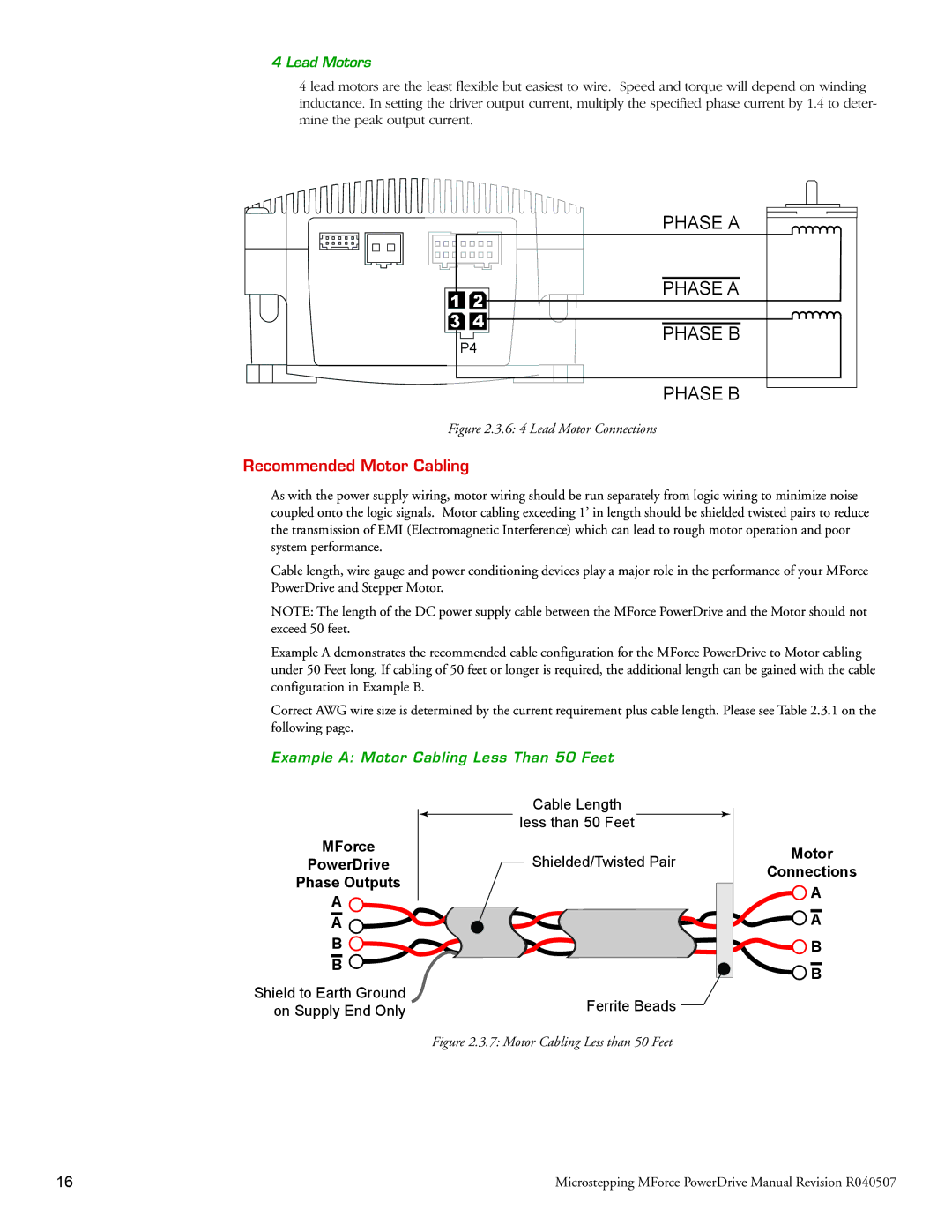
4 lead motors are the least flexible but easiest to wire. Speed and torque will depend on winding inductance. In setting the driver output current, multiply the specified phase current by 1.4 to deter- mine the peak output current.
1 | 2 |
3 | 4 |
P4 | |
PHASE A
PHASE A
PHASE B
PHASE B
Figure 2.3.6: 4 Lead Motor Connections
Recommended Motor Cabling
As with the power supply wiring, motor wiring should be run separately from logic wiring to minimize noise coupled onto the logic signals. Motor cabling exceeding 1’ in length should be shielded twisted pairs to reduce the transmission of EMI (Electromagnetic Interference) which can lead to rough motor operation and poor system performance.
Cable length, wire gauge and power conditioning devices play a major role in the performance of your MForce PowerDrive and Stepper Motor.
NOTE: The length of the DC power supply cable between the MForce PowerDrive and the Motor should not exceed 50 feet.
Example A demonstrates the recommended cable configuration for the MForce PowerDrive to Motor cabling under 50 Feet long. If cabling of 50 feet or longer is required, the additional length can be gained with the cable configuration in Example B.
Correct AWG wire size is determined by the current requirement plus cable length. Please see Table 2.3.1 on the following page.
Example A: Motor Cabling Less Than 50 Feet
MForce
PowerDrive
Phase Outputs
A ![]()
A
B ![]()
B ![]()
Shield to Earth Ground on Supply End Only
Cable Length
![]() less than 50 Feet
less than 50 Feet ![]()
Shielded/Twisted Pair
Ferrite Beads ![]()
Figure 2.3.7: Motor Cabling Less than 50 Feet
Motor
Connections
![]() A
A
![]() A
A
![]() B
B ![]() B
B
16 | Microstepping MForce PowerDrive Manual Revision R040507 |