APPENDIX C
Optional Prototype Development Cables
MD-CC300-000: USB to SPI Parameter Setup Cable
The
IMS SPI Interface Software communicates to the
Parameter Setup Cable through the PC's USB port.
The Parameter Setup Cable interprets SPI commands |
|
and sends these commands to the MForce |
|
PowerDrive through the SPI interface. | Figure A.1: |
Supplied Components: |
|
Setup Cable, USB Cable, USB Drivers, IMS SPI Interface Software. |
|
WARNING! DO NOT connect or disconnect the
Cable from MForce while power is applied!
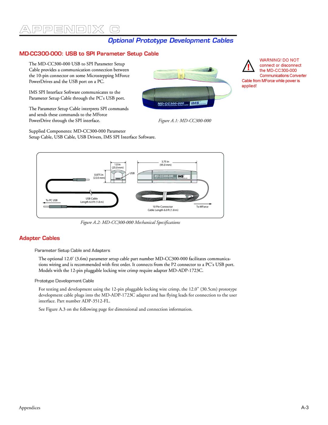
1.0 in | 3.75 in |
|
(95.0 mm) |
| |
(25.0 mm) |
|
|
0.875 in | USB |
|
|
| |
(22.0 mm) |
| |
USB to SPI Parameter Setup Cable | www.imshome.com |
To PC USB | USB Cable | |
Length 6.0 ft (1.8 m) | ||
|
10 Pin Connector | To MForce |
Cable Length 6.0 ft (1.8 m) |
|
Figure A.2: MD-CC300-000 Mechanical Specifications
Adapter Cables
Parameter Setup Cable and Adapters
The optional 12.0' (3.6m) parameter setup cable part number
Prototype Development Cable
For testing and development using the
See Figure A.3 on the following page for dimensional and connection information.
Appendices |