SECTION 1.2
Microstepping MForce PowerDrive Detailed Specifications
General Specifications
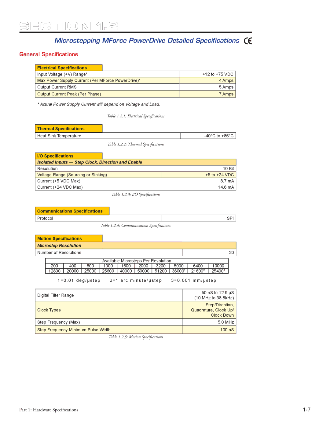
Electrical Specifications
Input Voltage (+V) Range* | +12 to +75 VDC |
Max Power Supply Current (Per MForce PowerDrive)* | 4 Amps |
Output Current RMS | 5 Amps |
Output Current Peak (Per Phase) | 7 Amps |
*Actual Power Supply Current will depend on Voltage and Load.
Table 1.2.1: Electrical Specifications
Thermal Specifications
Heat Sink Temperature
| Table 1.2.2: Thermal Specifications |
| ||
|
|
|
|
|
I/O Specifications |
|
|
|
|
Isolated Inputs — Step Clock, Direction and Enable |
| |||
Resolution |
| 10 Bit | ||
Voltage Range (Sourcing or Sinking) |
| +5 to +24 VDC | ||
Current (+5 VDC Max) |
| 8.7 mA | ||
Current (+24 VDC Max) |
| 14.6 mA | ||
|
| Table 1.2.3: I/O Specifications |
| |
|
|
| ||
Communications Specifications |
|
|
| |
Protocol
SPI
Table 1.2.4: Communications Specifications
Motion Specifications
Microstep Resolution
Number of Resolutions |
|
|
|
|
|
|
|
|
| 20 | ||||
|
|
|
|
|
|
|
|
|
|
|
|
|
| |
|
|
|
|
| Available Microsteps Per Revolution |
|
|
|
| |||||
| 200 | 400 | 800 |
| 1000 | 1600 | 2000 | 3200 | 5000 | 6400 |
| 10000 |
| |
| 12800 | 20000 | 25000 |
| 25600 | 40000 | 50000 | 51200 | 360001 | 216002 |
| 254003 |
| |
| 1 = 0 . 0 1 d e g / µ s t e p | 2 = 1 a r c m i n u t e / µ s t e p | 3 = 0 . 0 0 1 m m / µ s t e p | |||||||||||
|
|
|
|
|
|
|
|
|
|
|
|
|
| |
Digital Filter Range |
|
|
|
|
|
|
|
| 50 nS to 12.9 µS | |||||
|
|
|
|
|
|
|
| (10 MHz to 38.8kHz) | ||||||
|
|
|
|
|
|
|
|
|
|
| ||||
|
|
|
|
|
|
|
|
|
|
|
| Step/Direction, | ||
Clock Types |
|
|
|
|
|
|
|
|
| Quadrature, Clock Up/ | ||||
|
|
|
|
|
|
|
|
|
|
|
|
| Clock Down | |
Step Frequency (Max) |
|
|
|
|
|
|
|
|
|
| 5.0 MHz | |||
Step Frequency Minimum Pulse Width |
|
|
|
|
|
|
| 100 nS | ||||||
|
|
|
|
|
|
|
|
|
|
|
|
|
|
|
|
|
|
|
| Table 1.2.5: Motion Specifications |
|
|
|
|
|
| |||
Part 1: Hardware Specifications |
