Setup Parameters
The following table illustrates the setup parameters. These are easily configured using the IMS SPI Motor Interface configuration utility. An optional Parameter Setup Cable is available and recommended with the first order.
Microstepping MForce PowerDrive Setup Parameters
Name | Function | Range | Units | Default | |
|
|
|
|
| |
MHC | Motor Hold Current | 0 to 100 | percent | 5 | |
|
|
|
|
| |
MRC | Motor Run Current | 1 to 100 | percent | 25 | |
|
|
|
|
| |
|
| 1, 2, 4, 5, 8, 10, 16, 25, 32, 50, | µsteps per |
| |
MSEL | Microstep Resolution | 64, 100,108, 125, 127,128, | 256 | ||
full step | |||||
|
| 180, 200, 250, 256 |
| ||
|
|
|
| ||
DIR | Motor Direction Override | 0/1 | – | CW | |
|
|
|
|
| |
HCDT | Hold Current Delay Time | 0 or | mSec | 500 | |
|
|
|
|
| |
CLK TYPE | Clock Type | Step/Dir. Quadrature, Up/Down | – | Step/Dir | |
|
|
|
|
| |
CLK IOF | Clock and Direction Filter | 50 nS to 12.9 µS | nS (MHz) | 200nS(2.5 | |
(10 MHz to 38.8kHz) | MHz) | ||||
|
|
| |||
USER ID | User ID | Customizable | IMS | ||
|
|
|
|
| |
WARN TEMP | Warning Temperature | 0 to +125 | ºC | 80 | |
|
|
|
|
| |
EN ACT | Enable Active High/Low | High or Low | — | High | |
|
|
|
|
|
Table 1.2.6: Setup Parameters
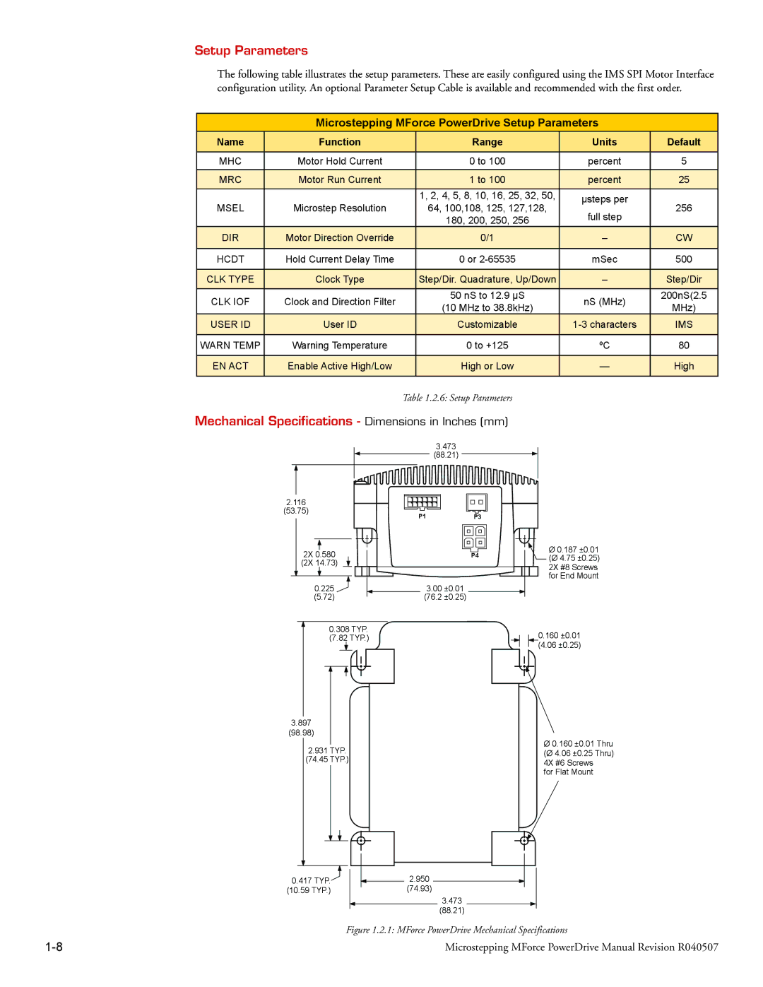
Mechanical Specifications - Dimensions in Inches (mm)
3.473
(88.21)
2.116 |
|
|
(53.75) | P1 | P3 |
|
2X | 0.580 |
| P4 |
(2X | 14.73) |
|
|
| 0.225 | 3.00 | ±0.01 |
| (5.72) | (76.2 | ±0.25) |
0.308 TYP.
(7.82 TYP.)
Ø 0.187 ±0.01 (Ø 4.75 ±0.25) 2X #8 Screws for End Mount
0.160 ±0.01
(4.06 ±0.25)
3.897
(98.98)
2.931 TYP.
(74.45 TYP.)
0.417 TYP.![]()
(10.59 TYP.)
Ø 0.160 ±0.01 Thru (Ø 4.06 ±0.25 Thru) 4X #6 Screws
for Flat Mount
2.950 (74.93)
3.473
(88.21)
Figure 1.2.1: MForce PowerDrive Mechanical Specifications
Microstepping MForce PowerDrive Manual Revision R040507 |