Basic DC Power Connection
Unregulated |
|
|
| |
Linear or |
| ! | WARNING! Do not connect | |
Switching |
| |||
| or disconnect cabling while | |||
Power Supply | ||||
power is applied! | ||||
|
| |||
Power |
|
|
| |
Ground |
|
|
| |
+VDC |
|
| Optional Prototype | |
|
|
| ||
|
|
| Development Cable: | |
|
| Shield to |
| |
|
|
| ||
| Earth Ground |
| ||
– +
P3 ![]()
![]()
![]()
![]()
Pin 2 Pin 1
WARNING! DO NOT connect or disconnect power leads
when power is applied! Disconnect the AC power side to power down the DC power supply.
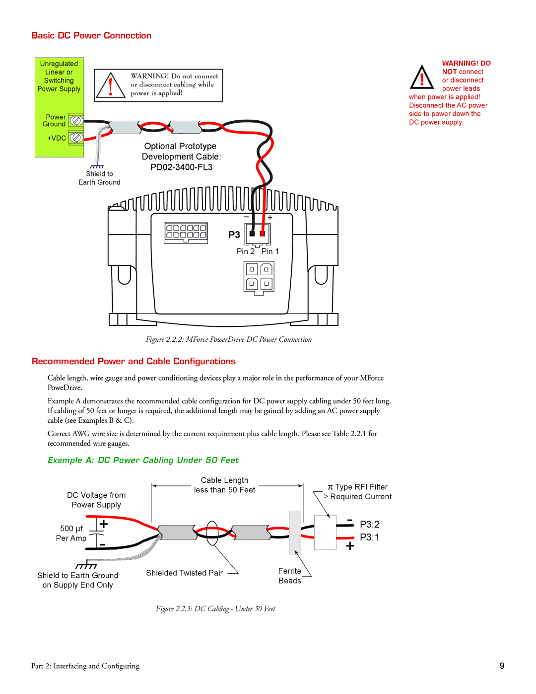
Figure 2.2.2: MForce PowerDrive DC Power Connection
Recommended Power and Cable Configurations
Cable length, wire gauge and power conditioning devices play a major role in the performance of your MForce PoweDrive.
Example A demonstrates the recommended cable configuration for DC power supply cabling under 50 feet long. If cabling of 50 feet or longer is required, the additional length may be gained by adding an AC power supply cable (see Examples B & C).
Correct AWG wire size is determined by the current requirement plus cable length. Please see Table 2.2.1 for recommended wire gauges.
Example A: DC Power Cabling Under 50 Feet
DC Voltage from
Power Supply
|
|
|
| |
500 µf |
| + | ||
|
|
|
|
|
Per Amp |
|
| - | |
|
| |||
Cable Length
![]() less than 50 Feet
less than 50 Feet ![]()
ΠType RFI Filter
ρRequired Current
-P3:2 + P3:1
Shield to Earth Ground | Shielded Twisted Pair | Ferrite |
on Supply End Only |
| Beads |
|
|
Figure 2.2.3: DC Cabling - Under 50 Feet
Part 2: Interfacing and Configuring