NEED A CABLE?
The following cables and converters are available to interface with P3:
2-Pin Locking Wire Crimp
P3 Connector - DC Power, 2-Pin Locking Wire Crimp
Pin Assignment - P3 Power
| Function | Description | |
Wire Crimp | |||
|
| ||
Pin 1 | +V | +12 to +75 VDC, 4 Amps Maximum per MDrive34Plus. | |
Pin 2 | GND | Power Supply Return. |
Table 1.2.8: P3 Connector
WARNING! Do not | Recommended Connector Shell and Pins | |
plug or unplug DC | ||
| ||
Power with power | Shell: Molex P/N | |
applied. | Pins: 2 x Molex P/N | |
| ||
| Wire: 18 AWG Shielded Twisted Pair |
P3 
![]()
![]() 2
2 ![]()
![]()
1
Figure 1.2.3: P3 — 2-Pin Locking Wire Crimp Pin Configuration
P4 Connector - Motor
NEED A CABLE? The following cables and converters are available to interface with P4:
4-Pin Locking Wire Crimp
Pin Assignment - P4 Motor
Function | Description | ||
Wire Crimp | |||
|
| ||
Pin 1 | Phase A | Phase A Motor Output | |
Pin 2 | Phase A | Phase A Motor Return | |
Pin 3 | Phase B | Phase B Motor Output | |
Pin 4 | Phase B | Phase B Motor Return | |
Recommended |
|
| |
Cable |
|
| |
|
| ||
|
| Table 1.2.9: P4 Connecter |
Recommended Connector Shell and Pins
Shell: Molex P/N
Pins: 4 x Molex P/N
Wire: 16 AWG Shielded Twisted Pair
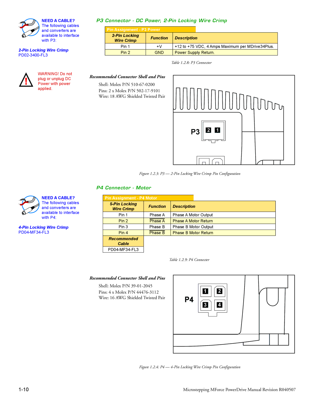
P4
1 | 2 |
3 | 4 |
Figure 1.2.4: P4 — 4-Pin Locking Wire Crimp Pin Configuration
Microstepping MForce PowerDrive Manual Revision R040507 |