Pin Assignment and Description
P1
Pin Assignment - P1 Power, I/O and SPI
Connections
Pin # | Function | Description | |
Pin 1 | N/C | No Connect | |
Pin 2 | N/C | No Connect | |
|
| The Signal applied to the Optocoupler Reference will | |
|
| determine the sinking/ or sourcing configuration of the inputs. | |
Pin 3 | Opto Reference | To set the inputs for sinking operation, a +5 to +24 VDC | |
|
| supply is connected. If sourcing, the Reference is connected | |
|
| to Ground. | |
|
| Step Clock input. The step clock input will receive the clock | |
Pin 4 | Step Clock/Channel | pulses which will step the motor 1 step for each pulse. It | |
A/ Clock Up | may also receive quadrature and clock up type inputs if so | ||
| |||
|
| configured. | |
|
| Enable/Disable Input will enable or disable the driver output | |
Pin 5 | Enable | to the motor. In the disconnected state the driver outputs are | |
|
| enabled in either sinking or sourcing configuration. | |
Pin 6 | Direction/Channel B/ | Direction input. The axis direction will be with respect to the | |
Clock Down | state of the Direction Override Parameter. It may also receive | ||
| quadrature and clock up type inputs if so configured. | ||
|
| ||
Pin 7 | +5 VDC Output | Supply voltage for the | |
Pin 8 | SPI Clock | The Clock is driven by the SPI Master. The clock cycles once | |
for each data bit. | |||
|
| ||
Pin 9 | GND | Communications Ground. | |
Pin 10 | MISO | ||
to the SPI Master. | |||
|
| ||
Pin 11 | CS | SPI Chip Select. This signal is used to turn communications | |
on multiple MFM units on or off. | |||
|
| ||
Pin 12 | MOSI | ||
to the MFM. | |||
|
| ||
| Table 1.2.7: P1 Connector – Power, I/O and SPI Communications | ||
1 | 3 | 5 | 7 | 9 | 11 |
2 | 4 | 6 | 8 | 10 | 12 |
|
| P1 |
|
| |
NEED A CABLE? The following cables and converters are available to interface with P1:
12-Pin Locking Wire Crimp
NEED A CABLE? The following cables and converters are available to interface communications with
USB to SPI:
All SPI Communications will connect to the P1 Connector.
An adapter is available to interface the
This adapter may be used in conjunction with the following Prototype Development cables to interface power and logic:
See Appendix A for details.
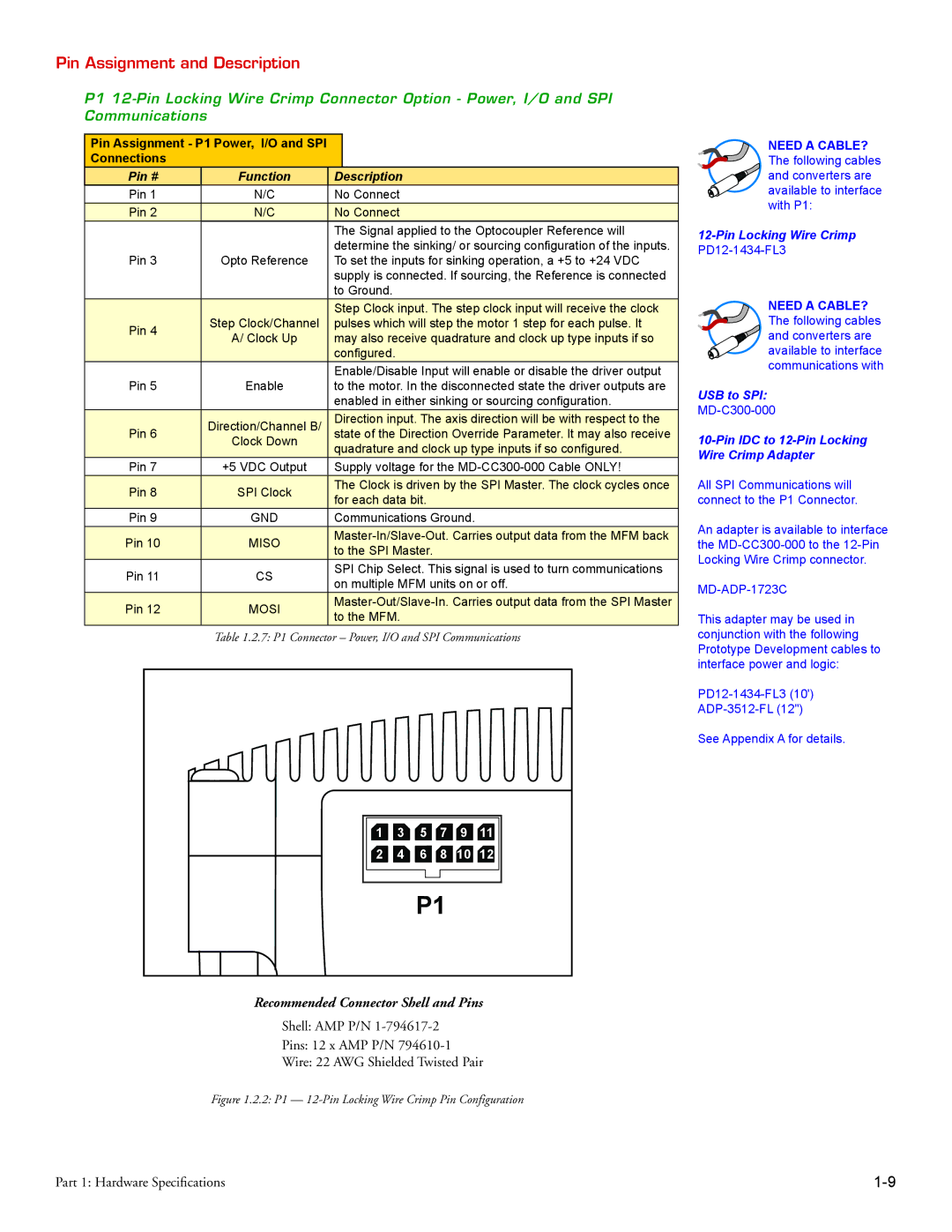
Recommended Connector Shell and Pins
Shell: AMP P/N
Pins: 12 x AMP P/N
Wire: 22 AWG Shielded Twisted Pair
Figure 1.2.2: P1 — 12-Pin Locking Wire Crimp Pin Configuration
Part 1: Hardware Specifications |