Minimum Required Connections
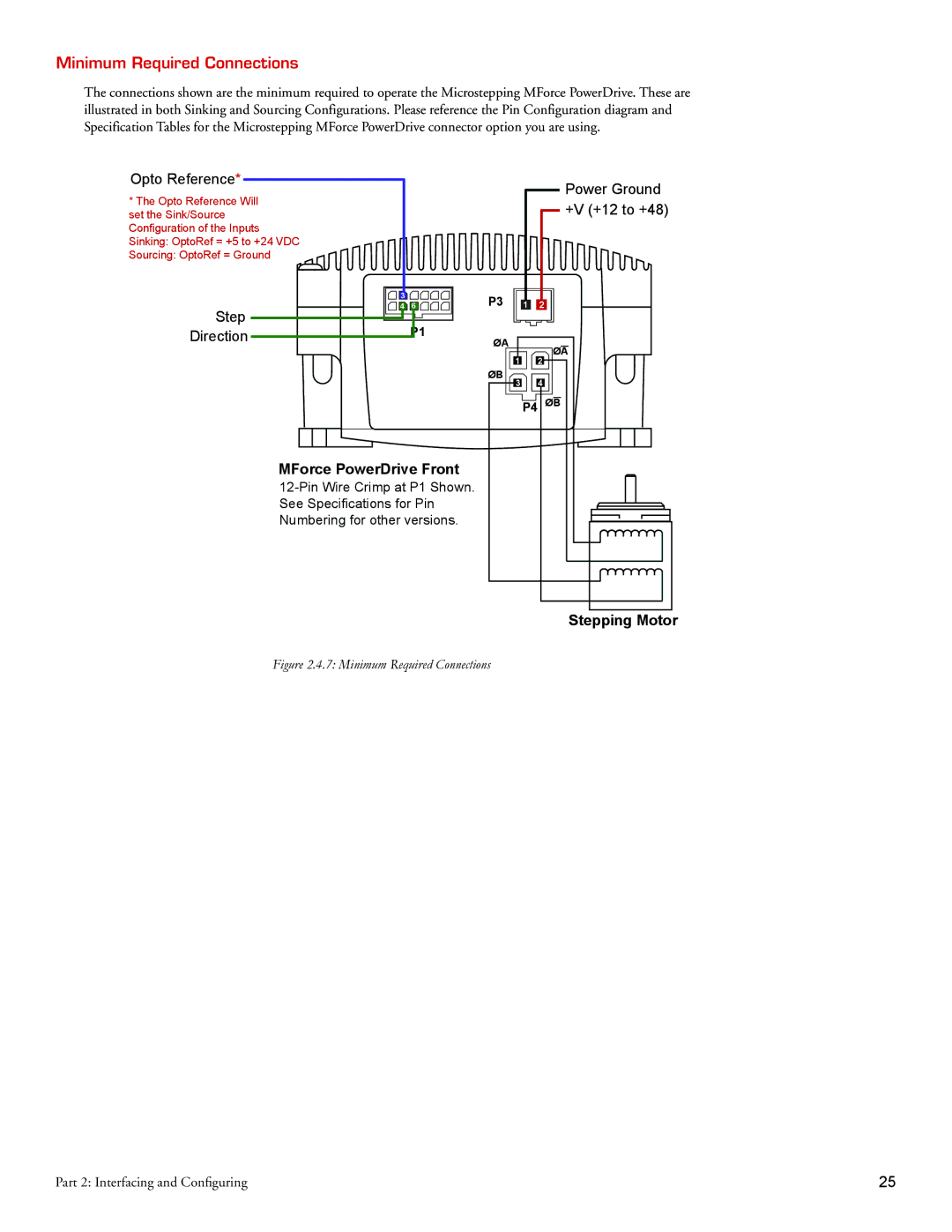
The connections shown are the minimum required to operate the Microstepping MForce PowerDrive. These are illustrated in both Sinking and Sourcing Configurations. Please reference the Pin Configuration diagram and Specification Tables for the Microstepping MForce PowerDrive connector option you are using.
Opto Reference* | Power Ground | |
* The Opto Reference Will | ||
+V (+12 to +48) | ||
set the Sink/Source | ||
Configuration of the Inputs |
| |
Sinking: OptoRef = +5 to +24 VDC |
| |
Sourcing: OptoRef = Ground |
|
| 3 | 6 | P3 |
| 1 | 2 |
Step | 4 |
| ||||
| P1 |
|
|
|
| |
Direction |
| ØA |
|
| ØA | |
|
|
|
|
| ||
|
|
|
| 1 |
| |
|
|
|
|
| 2 | |
|
|
| ØB | 3 |
| 4 |
|
|
|
|
| P4 ØB | |
MForce PowerDrive Front
Stepping Motor
Figure 2.4.7: Minimum Required Connections
Part 2: Interfacing and Configuring | 25 |