PD12-1434-FL3 — Power, I/O and SPI
The
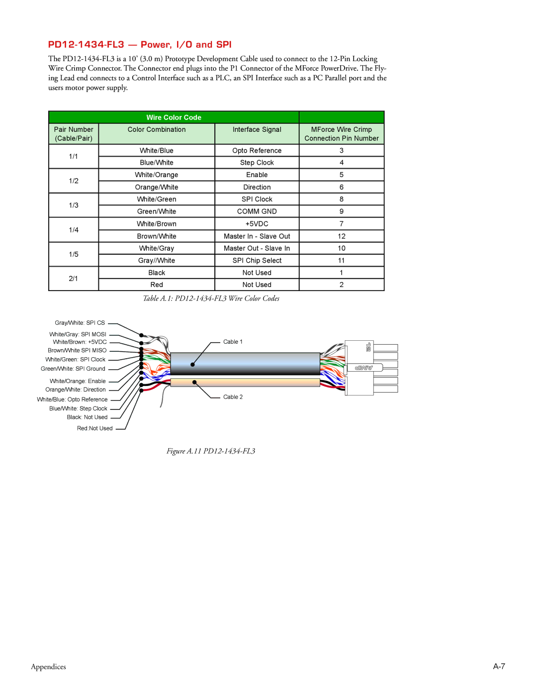
| Wire Color Code |
|
| |
Pair Number | Color Combination | Interface Signal | MForce Wire Crimp | |
(Cable/Pair) |
|
| Connection Pin Number | |
1/1 | White/Blue | Opto Reference | 3 | |
Blue/White | Step Clock | 4 | ||
| ||||
1/2 | White/Orange | Enable | 5 | |
Orange/White | Direction | 6 | ||
| ||||
1/3 | White/Green | SPI Clock | 8 | |
Green/White | COMM GND | 9 | ||
| ||||
1/4 | White/Brown | +5VDC | 7 | |
|
|
| ||
Brown/White | Master In - Slave Out | 12 | ||
| ||||
1/5 | White/Gray | Master Out - Slave In | 10 | |
Gray//White | SPI Chip Select | 11 | ||
| ||||
2/1 | Black | Not Used | 1 | |
Red | Not Used | 2 | ||
|
| Table A.1: | |
Gray/White: SPI CS |
| |
White/Gray: SPI MOSI | Cable 1 | |
White/Brown: +5VDC | ||
Brown/White SPI MISO |
| |
White/Green: SPI Clock |
| |
Green/White: SPI Ground |
| |
White/Orange: Enable |
| |
Orange/White: Direction | Cable 2 | |
White/Blue: Opto Reference | ||
| ||
Blue/White: Step Clock |
| |
Black: Not Used |
| |
Red:Not Used |
|
12
AMP
Figure A.11 PD12-1434-FL3
Appendices |