SPI Commands and Parameters
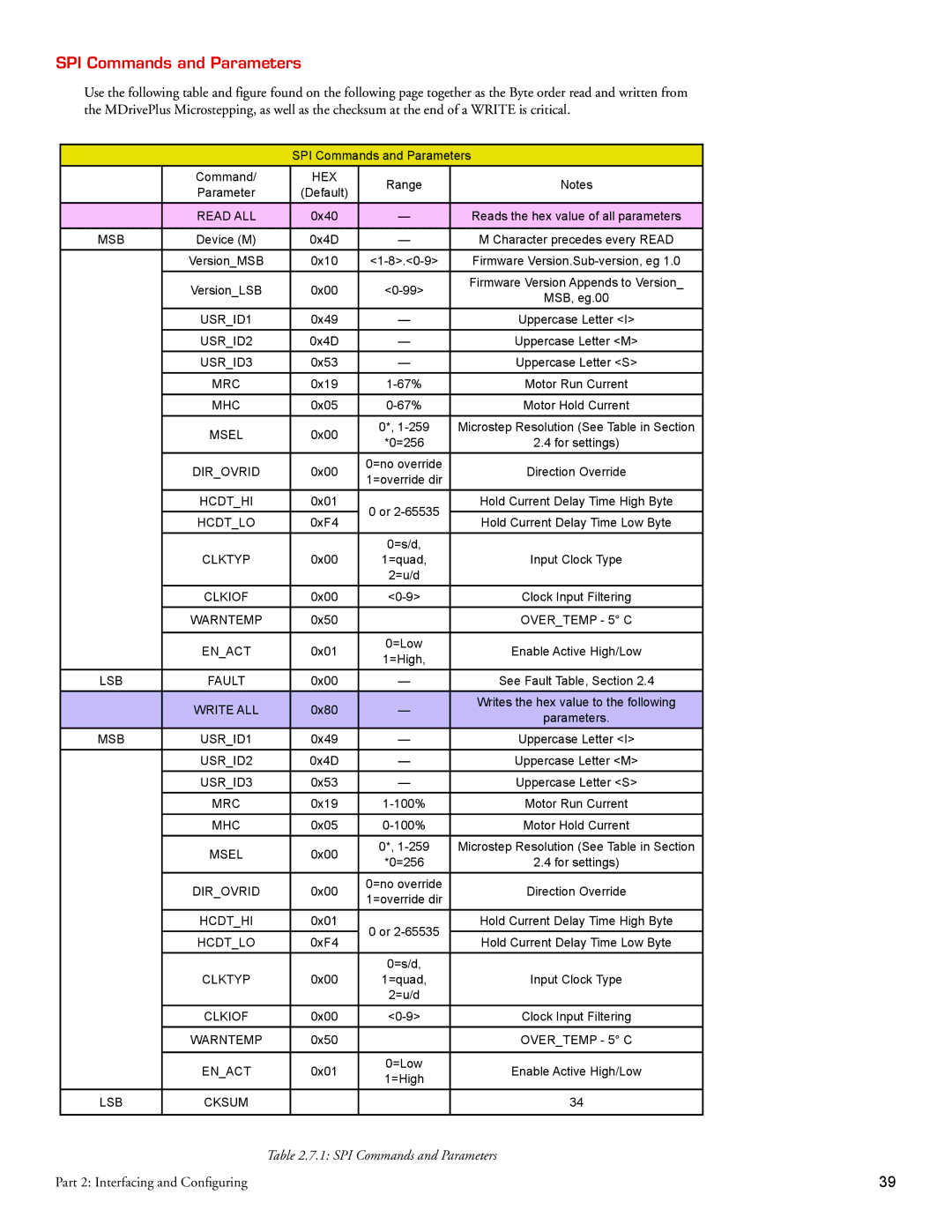
Use the following table and figure found on the following page together as the Byte order read and written from the MDrivePlus Microstepping, as well as the checksum at the end of a WRITE is critical.
|
| SPI Commands and Parameters | ||
| Command/ | HEX | Range | Notes |
| Parameter | (Default) | ||
|
|
| ||
| READ ALL | 0x40 | — | Reads the hex value of all parameters |
|
|
|
|
|
MSB | Device (M) | 0x4D | — | M Character precedes every READ |
| Version_MSB | 0x10 | Firmware | |
| Version_LSB | 0x00 | Firmware Version Appends to Version_ | |
| MSB, eg.00 | |||
|
|
|
| |
| USR_ID1 | 0x49 | — | Uppercase Letter <I> |
| USR_ID2 | 0x4D | — | Uppercase Letter <M> |
| USR_ID3 | 0x53 | — | Uppercase Letter <S> |
| MRC | 0x19 | Motor Run Current | |
| MHC | 0x05 | Motor Hold Current | |
| MSEL | 0x00 | 0*, | Microstep Resolution (See Table in Section |
| *0=256 | 2.4 for settings) | ||
|
|
| ||
| DIR_OVRID | 0x00 | 0=no override | Direction Override |
| 1=override dir | |||
|
|
|
| |
| HCDT_HI | 0x01 | 0 or | Hold Current Delay Time High Byte |
|
|
|
| |
| HCDT_LO | 0xF4 | Hold Current Delay Time Low Byte | |
|
| |||
|
|
| 0=s/d, |
|
| CLKTYP | 0x00 | 1=quad, | Input Clock Type |
|
|
| 2=u/d |
|
| CLKIOF | 0x00 | Clock Input Filtering | |
| WARNTEMP | 0x50 |
| OVER_TEMP - 5° C |
|
|
|
|
|
| EN_ACT | 0x01 | 0=Low | Enable Active High/Low |
| 1=High, | |||
|
|
|
| |
LSB | FAULT | 0x00 | — | See Fault Table, Section 2.4 |
| WRITE ALL | 0x80 | — | Writes the hex value to the following |
| parameters. | |||
|
|
|
| |
MSB | USR_ID1 | 0x49 | — | Uppercase Letter <I> |
| USR_ID2 | 0x4D | — | Uppercase Letter <M> |
| USR_ID3 | 0x53 | — | Uppercase Letter <S> |
| MRC | 0x19 | Motor Run Current | |
| MHC | 0x05 | Motor Hold Current | |
| MSEL | 0x00 | 0*, | Microstep Resolution (See Table in Section |
| *0=256 | 2.4 for settings) | ||
|
|
| ||
| DIR_OVRID | 0x00 | 0=no override | Direction Override |
| 1=override dir | |||
|
|
|
| |
| HCDT_HI | 0x01 | 0 or | Hold Current Delay Time High Byte |
| HCDT_LO | 0xF4 | Hold Current Delay Time Low Byte | |
|
| |||
|
|
| 0=s/d, |
|
| CLKTYP | 0x00 | 1=quad, | Input Clock Type |
|
|
| 2=u/d |
|
| CLKIOF | 0x00 | Clock Input Filtering | |
| WARNTEMP | 0x50 |
| OVER_TEMP - 5° C |
|
|
|
|
|
| EN_ACT | 0x01 | 0=Low | Enable Active High/Low |
| 1=High | |||
|
|
|
| |
LSB | CKSUM |
|
| 34 |
|
|
|
|
|
| Table 2.7.1: SPI Commands and Parameters |
Part 2: Interfacing and Configuring | 39 |
