WARNING! DO NOT connect or disconnect power leads
when power is applied! Disconnect the AC power side to power down the DC power supply.
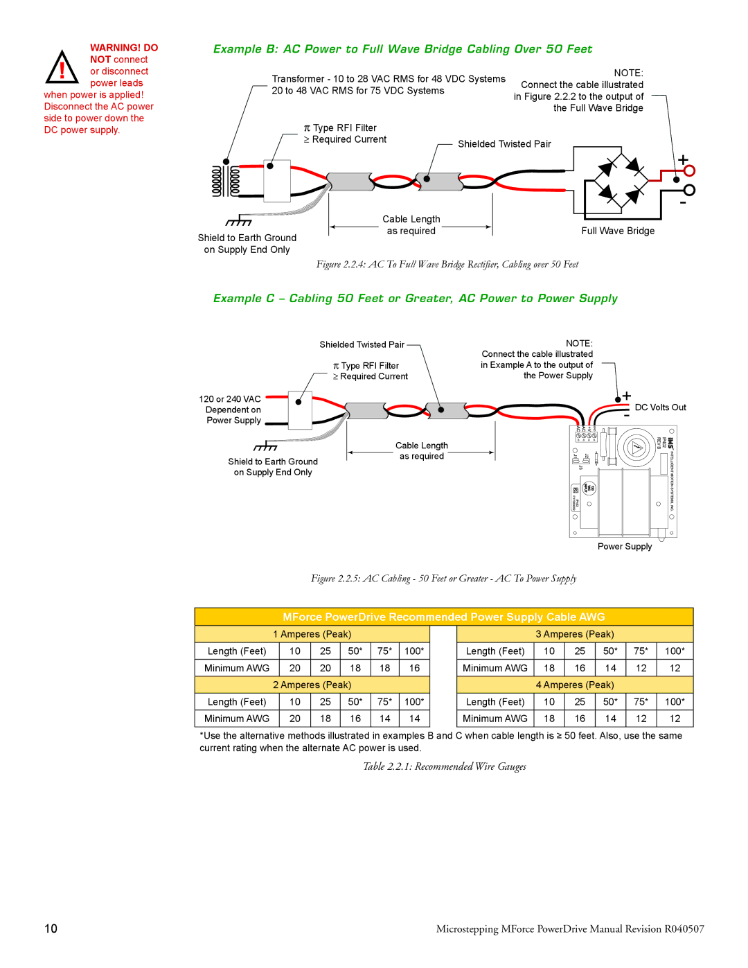
Example B: AC Power to Full Wave Bridge Cabling Over 50 Feet
Transformer - 10 to 28 VAC RMS for 48 VDC Systems | NOTE: | |
Connect the cable illustrated | ||
20 to 48 VAC RMS for 75 VDC Systems | ||
in Figure 2.2.2 to the output of | ||
| ||
| the Full Wave Bridge |
ΠType RFI Filter
ρ Required Current | Shielded Twisted Pair |
| |
| + |
Shield to Earth Ground
on Supply End Only
Cable Length
as required
- |
Full Wave Bridge
Figure 2.2.4: AC To Full Wave Bridge Rectifier, Cabling over 50 Feet
Example C – Cabling 50 Feet or Greater, AC Power to Power Supply
| Shielded Twisted Pair | NOTE: |
| Π Type RFI Filter | Connect the cable illustrated |
| in Example A to the output of | |
| ρ Required Current | the Power Supply |
120 or 240 VAC |
| + DC Volts Out |
Dependent on |
| |
Power Supply |
| - |
| Cable Length |
|
Shield to Earth Ground | as required |
|
|
| |
on Supply End Only |
|
|
Power Supply
Figure 2.2.5: AC Cabling - 50 Feet or Greater - AC To Power Supply
MForce PowerDrive Recommended Power Supply Cable AWG
| 1 Amperes (Peak) |
|
|
| 3 Amperes (Peak) |
|
| ||||
Length (Feet) | 10 | 25 | 50* | 75* | 100* | Length (Feet) | 10 | 25 | 50* | 75* | 100* |
Minimum AWG | 20 | 20 | 18 | 18 | 16 | Minimum AWG | 18 | 16 | 14 | 12 | 12 |
| 2 Amperes (Peak) |
|
|
| 4 Amperes (Peak) |
|
| ||||
Length (Feet) | 10 | 25 | 50* | 75* | 100* | Length (Feet) | 10 | 25 | 50* | 75* | 100* |
Minimum AWG | 20 | 18 | 16 | 14 | 14 | Minimum AWG | 18 | 16 | 14 | 12 | 12 |
*Use the alternative methods illustrated in examples B and C when cable length is ≥ 50 feet. Also, use the same current rating when the alternate AC power is used.
Table 2.2.1: Recommended Wire Gauges
10 | Microstepping MForce PowerDrive Manual Revision R040507 |
