STEP/DIRECTION TIMING
|
|
|
| TDH |
|
|
Direction |
|
| ||||
|
| TDSU |
|
|
|
|
|
|
|
|
| ||
Step |
| TSL | ||||
|
|
|
| TSH |
| |
QUADRATURE TIMING
Direction Change | TCHL |
| |
Channel A |
|
| TDC |
Channel B |
|
| TCHL |
UP/DOWN TIMING
Step Up |
|
|
|
|
|
|
|
|
Step Down | TSH | TSL | TDC |
|
|
| TDC |
|
|
|
|
|
|
|
|
| |
|
|
|
| TSH | TSL |
|
| |
|
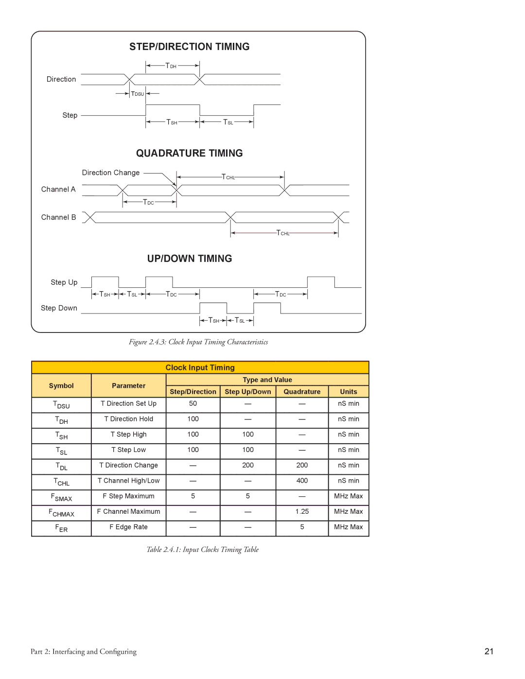
| Figure 2.4.3: Clock Input Timing Characteristics |
|
| ||||
|
|
|
|
|
|
| ||
|
|
| Clock Input Timing |
|
| |||
Symbol |
| Parameter |
|
|
| Type and Value |
| |
| Step/Direction |
| Step Up/Down | Quadrature | Units | |||
|
|
|
| |||||
TDSU | T Direction Set Up | 50 |
|
| — | — | nS min | |
TDH | T Direction Hold | 100 |
|
| — | — | nS min | |
TSH |
| T Step High | 100 |
|
| 100 | — | nS min |
TSL |
| T Step Low | 100 |
|
| 100 | — | nS min |
TDL | T Direction Change | — |
| 200 | 200 | nS min | ||
TCHL | T Channel High/Low | — |
| — | 400 | nS min | ||
FSMAX | F Step Maximum | 5 |
|
| 5 | — | MHz Max | |
FCHMAX | F Channel Maximum | — |
| — | 1.25 | MHz Max | ||
FER | F Edge Rate | — |
| — | 5 | MHz Max | ||
Table 2.4.1: Input Clocks Timing Table
Part 2: Interfacing and Configuring | 21 |
