Appareils DE Chauffage Individuels À AIR Forcé
108954
Table of Contents
Portable Forced AIR Heaters
Safety Information
Unpacking
Assembly
Product Identification
For Model GK30 only
Fuels Theory of Operation
Ventilation
Operation
STORING, TRANSPORTING, or Shipping
How Often How To
Preventative Maintenance Schedule
Troubleshooting
See Wiring Diagram,
See Nozzle Assembly,
Diagram,
See Fuel Filter,
Fuel Filter
Service Procedures
Upper Shell Removal
Model GK20
Disconnecting Ignitor Wires from Ignition Control Assembly
Ignitor
Pump Pressure Adjustment
AIR OUTPUT, AIR INTAKE, and Lint Filters
Nozzle Assembly
Airline Replacement and Proper Routing,
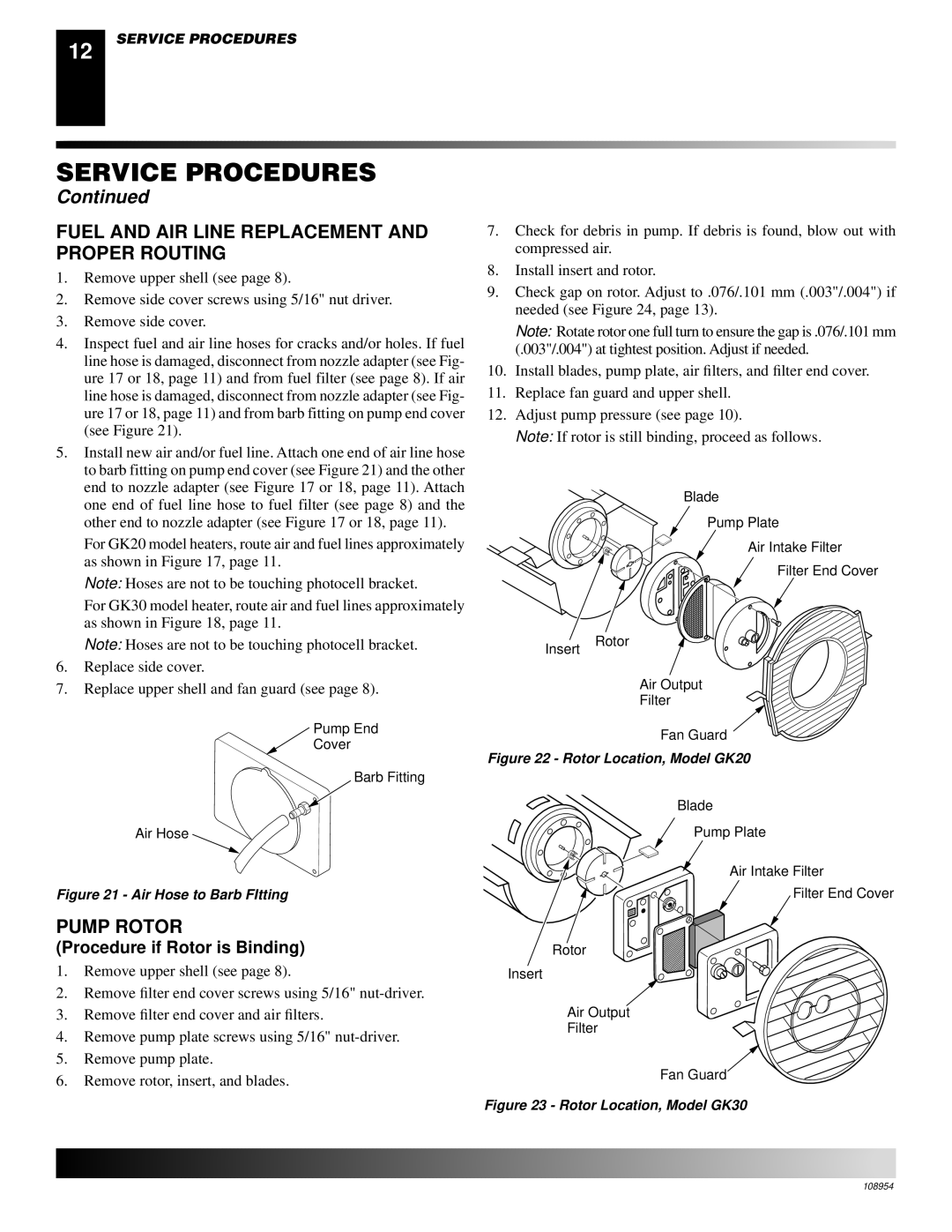
Pump Rotor
Fuel and AIR Line Replacement and Proper Routing
Procedure if Rotor is Binding
Reinstall insert and rotor Perform steps 10 through 12,
Ignition Control Assembly
Remove Old Assembly
FAN
Service Procedures Wiring Diagram
Installing the New Assembly
Specifications
Accessories
Model GK20
Motor and Pump Assembly
Illustrated Parts Breakdown
Parts List
Number Description QTY
Model GK30
KEY Part Number Description QTY
Wheels and Handles
KEY Part Number Description QTY
EC Conformity Declaration
BIEMMEDUE, S.p.A Via Industria Cherasco CN
Italia
Riscaldatori Mobili AD Aria Forzata
Funzione il riscaldatore
Informazioni Sulla Sicurezza
Avvertenze
Assemblaggio
Identificazione DEI Prodotti
Disimballaggio
PER I Soli Modello GK30
Combustibili Principi DI Funzionamento
Ventilazione
Accensione DEL Riscaldatore
Funzionamento
CONSERVAZIONE, Trasporto O Spedizione
Spegnimento DEL Riscaldatore
Vedere Ventola a pagina
Programma DI Manutenzione Preventiva
Articolo Frequenza
Individuazione DEI Guasti
Avvertenza alta tensione
Controllo dell’accensione lo spegne dopo un
Avvia Elettrico sia resettato
Diagrammi
Vedere Filtri di ingresso e di uscita
Filtro DEL Combustibile
Procedure DI Manutenzione
Rimozione DEL Semiguscio Superiore
Modello GK20
Accenditore
Figura 12. Sostituzione dell’accenditore
Pressione del Modello compressore bar/psi
Regolazione Della Pressione DEL Compressore
Importante non oliare i filtri
Ugello
Dell’aria a pagina
Sostituzione E Posa DEI Tubi DEL Combustibile E DELL’ARIA
Rotore DEL Compressore
Ventola
Figura 25. Carteggiatura del rotore
Rimozione del gruppo vecchio
Installazione del gruppo nuovo
Gruppo DI Controllo DELL’ACCENSIONE
Gruppo del motore e del compressore
Veduta Esplosa DEI Componenti
Modello GK20
Distinta DEI Componenti
Numero DI Descrizione Catalogo DEL Pezzo
Modello GK30
Controdado esagonale 105880-01 Fusibile
Ruote ED Impugnature
Numero DI Descrizione Catalogo DEL Pezzo
Portata nominale KW Combustibile
Diagrammi Schematici DEI Collegamenti Elettrici
Dati Tecnici
KIT Delle Ruote E DELL’IMPUGNATURA Standard HA1206
Accessori
Manometro HA1180
Disponibili presso il concessionario locale
Dichiarazione DI Conformità CE
Italia
Appareils DE Chauffage Individuels À AIR Forcé
Table DES Marières
Avertissements
Montage
Nomenclature DES Pièces
Déballage
Pour Modè LE GK30
Carburants
Principes DE Fonctionnement
Conditions Requises Pour LES Rallonges É Lectriques
ENTREPOSAGE, Transport OU Expédition
Mise EN Marche DE L’APPAREIL
Pour Arrê TER L’APPAREIL DE Chauffage
Lé ment Pé riodicité Opé ration
Tableau D’ENTRETIEN Préventif
Dépannage
Avertissement Haute tension
Entreposage, transport ou expédition
Voir Réglage de la pression de la
Voir Filtre à carburant ,
Schéma électrique ,
Filtre À Carburant
Procédures D’ENTRETIEN
DÉ Pose DU Couvercle
Modè le GK20
Dé branchement des fils d’allumeur de la commande d’allumage
Allumeur
Filtres DE Sortie D’AIR, D’ENTRÉ E D’AIR ET À Peluche
RÉ Glage DE LA Pression DE LA Pompe
Gicleur
Dé pose de lensemble gicleur-adaptateur
Rotor DE LA Pompe
Procé dure en cas de grippage
Emplacement des vis de ré glage de l’é cart
Ventilateur
Dé pose des piè ces existantes
Commande D’ALLUMAGE
Installation des piè ces neuves
Lectroniques
Schémas Électriques
Accessoires
Spécifications
VUE Éclatée
GK20
Liste DES Pièces
RÉ F DE PIÈ CE DÉ Signation
GK30
Ensemble moteur et pompe
˚ DE Numé RO RÉ F DE PIÈ CE DÉ Signation QTÉ
Roues ET Guidons
Modè LE GK30
Déclaration DE Conformité À LA CE
Italia
Tragbare Hochdruck Heissluftturbinen
Inhaltsverzeichnis
Gefahr Eine Kohlenmonoxydvergiftung kann tödlich sein
Sicherheitsinformationen
Warnhinweise
Vorschriften zu erfolgen
Auspacken
Produktbeschreibung
Zusammenbau
NUR FÜ R GK30 Modell
Kraftstoffearbeitsweise
Entlüftung
Bedienung
LAGERUNG, TRANSPORT, Versand
Teil Hä ufigkeit Durchfü hrung
Regelmässige Wartung
Fehlersuche
Siehe Lagerung, Transport oder Versand
Siehe Pumpendruckeinstellung auf
Rung, Transport, Versand auf Seite
Kraftstoffilter
Wartungsverfahren
Entfernen DES Oberen Gehä Uses
GK30 Modell
ZÜ Nder
Pumpendruckeinstellung
LUFTAUSLASS-,LUFTEINLASS-UNDSTAUB- Filter
DÜ Senbaugruppe
Verfahren, wenn die Pumpe festgefressen ist
Entfernen DER KRAFTSTOFF- UND Luftschlä Uche UND Verlegung
Pumpenrotor
LÜ Fter
Die Lüfterabdeckung und das obere Gehäuse wieder anbringen
Neue Baugruppe montieren
ZÜ Ndstromanlage
Alte Baugruppe entfernen
Zusatzgeräte
Technische Daten
Schaltplan
Zusatzgeräte sind bei Ihrem zuständigen Händler erhältlich
Bebilderte Ersatzteilliste
Motor- und Pumpenbaugruppe
Ersatzteilkatalog
Teilnummer Beschreibung STÜ CK
GK30 Modell
Kenn Teilnummer Beschreibung STÜ CK
Räder UND Handgriffe
GK30 Modell
EU-ÜBEREINSTIMMUNGSERKLÄRUNG
Tragbare Hochdruck-Heizluftturbinen Modellnummern GK20, GK30
Italia
108954
Not a UPCRev. a