POWERMATE3
This dialog is used to change the user preset‘s descrip- tion. Turn the MENU/ENTER rotary encoder to the left or right to edit the highlighted character. Pressing the MENU/ENTER rotary encoder accepts the desired symbol and moves the cursor to the next character. Move the cur- sor to the left or to the right by pressing the or func- tion keys. Select the ↵ symbol or press the OK function key to quit editing the name. Pressing the BACK function key returns to the menu.
USB RECORD ROUTING
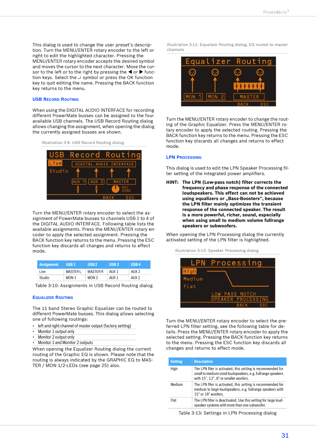
When using the DIGITAL AUDIO INTERFACE for recording different PowerMate busses can be assigned to the four available USB channels. The USB Record Routing dialog allows changing the assignment, when opening the dialog the currently assigned busses are shown.
Illustration
USB Record Routing
| Live |
|
|
|
|
|
|
|
|
|
|
|
|
DIGITAL AUDIO INTERFACE |
| ||||||||||||
| Studio |
|
|
|
|
|
|
|
|
|
|
| |
|
|
|
|
|
|
|
|
|
|
|
| ||
|
|
|
|
|
|
|
|
|
|
| |||
|
|
|
|
|
|
|
|
|
|
|
|
|
|
|
|
|
|
|
|
|
|
|
|
|
|
| |
|
|
| AUX 1 |
| AUX 2 |
|
| MASTER |
| ||||
|
|
|
|
|
|
|
|
|
|
| REC | ||
|
|
|
|
|
|
|
|
|
|
| |||
|
|
|
|
|
|
|
|
|
| ||||
|
|
|
|
|
|
|
|
|
|
| SEND | ||
BACK ESC
Turn the MENU/ENTER rotary encoder to select the as- signment of PowerMate busses to channels USB 1 to 4 of the DIGITAL AUDIO INTERFACE. Following table lists the available assignments. Press the MENU/ENTER rotary en- coder to apply the selected assignment. Pressing the BACK function key returns to the menu. Pressing the ESC function key discards all changes and returns to effect mode.
Assignment | USB 1 | USB 2 | USB 3 | USB 4 |
|
|
|
|
|
Live | MASTER L | MASTER R | AUX 1 | AUX 2 |
|
|
|
|
|
Studio | MON 1 | MON 2 | AUX 1 | AUX 2 |
|
|
|
|
|
Table
EQUALIZER ROUTING
The 11 band Stereo Graphic Equalizer can be routed to different PowerMate busses. This dialog allows selecting one of following routings:
•left and right channel of master output (factory setting)
•Monitor 1 output only
•Monitor 2 output only
•Monitor 1 and Monitor 2 outputs
When opening the Equalizer Routing dialog the current routing of the Graphic EQ is shown. Please note that the routing is always indicated by the GRAPHIC EQ to MAS- TER / MON
Illustration
Equalizer Routing
| MON 1 |
| MON 2 |
| MASTER |
|
|
|
|
|
|
|
|
| |
|
|
|
|
| BACK | ESC | |
Turn the MENU/ENTER rotary encoder to change the rout- ing of the Graphic Equalizer. Press the MENU/ENTER ro- tary encoder to apply the selected routing. Pressing the BACK function key returns to the menu. Pressing the ESC function key discards all changes and returns to effect mode.
LPN PROCESSING
This dialog is used to edit the LPN Speaker Processing fil- ter setting of the integrated power amplifiers.
HINT: The LPN
When opening the LPN Processing dialog the currently activated setting of the LPN filter is highlighted.
Illustration
LPN Processing
High
Medium
Flat
LOW PASS NOTCH
SPEAKER PROCESSING
BACK | ESC |
Turn the MENU/ENTER rotary encoder to select the pre- ferred LPN filter setting, see the following table for de- tails. Press the MENU/ENTER rotary encoder to apply the selected setting. Pressing the BACK function key returns to the menu. Pressing the ESC function key discards all changes and returns to effect mode.
Setting | Description |
|
|
High | The LPN flter is activated, this setting is recommended for |
| small to medium sized loudspeakers, e.g. fullrange speakers |
| with 15“, 12“, 8“ or smaller woofers. |
|
|
Medium | The LPN flter is activated, this setting is recommended for |
| medium to large loudspeakers, e.g. fullrange speakers with |
| 15“ or 18“ woofers. |
|
|
Flat | The LPN filter is deactivated. Use this setting for large loud- |
| speaker systems with more than one subwoofer. |
|
|
Table
31