POWERMATE3
72 - AMPLIFIER STATUS INDICATORS
These indicators are to inform you about the actual operational state of the PowerMate’s internal power amplifier.
PROTECT LED
The PROTECT indicator lights when one of the PowerMate’s extensive protection circuits – against thermal overload,
In this case you should first check whether the ventilation louvers are blocked. Another cause could be, that you have connected more than three 8 ohms speaker systems per power output. Please also disconnect the Speakon connectors and check the speaker cables for short circuits. During
LIMIT LED
The LIMIT indicator signals that you are operating the PowerMate at the internal power amp’s limit. Frequent blinking of the LED is acceptable, since the amplifier’s incorporated clip limiter prevents distortion. Continuous lighting indi- cates that you have to be aware of degradation in the outputted sound. In that case, the master level has to be reduced. The LIMIT LED also lights if the output level is reduced because of high amplifier temperature or activated Speaker Pro- tection (see page 32).
2.9 Rear panel
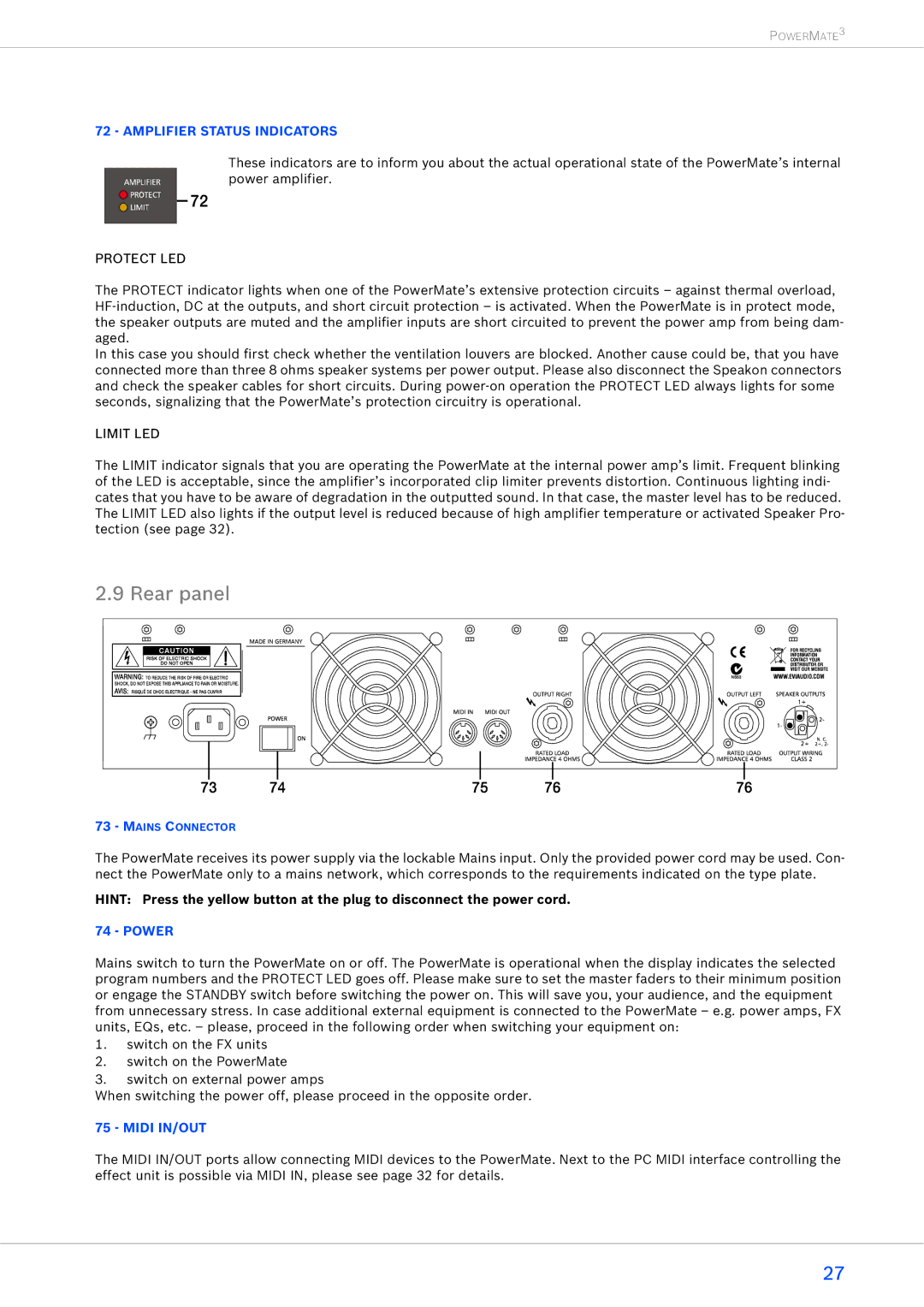
73- MAINS CONNECTOR
The PowerMate receives its power supply via the lockable Mains input. Only the provided power cord may be used. Con- nect the PowerMate only to a mains network, which corresponds to the requirements indicated on the type plate.
HINT: Press the yellow button at the plug to disconnect the power cord.
74 - POWER
Mains switch to turn the PowerMate on or off. The PowerMate is operational when the display indicates the selected program numbers and the PROTECT LED goes off. Please make sure to set the master faders to their minimum position or engage the STANDBY switch before switching the power on. This will save you, your audience, and the equipment from unnecessary stress. In case additional external equipment is connected to the PowerMate – e.g. power amps, FX units, EQs, etc. – please, proceed in the following order when switching your equipment on:
1.switch on the FX units
2.switch on the PowerMate
3.switch on external power amps
When switching the power off, please proceed in the opposite order.
75 - MIDI IN/OUT
The MIDI IN/OUT ports allow connecting MIDI devices to the PowerMate. Next to the PC MIDI interface controlling the effect unit is possible via MIDI IN, please see page 32 for details.
27
