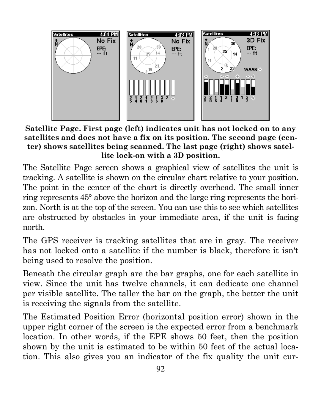
Satellite Page. First page (left) indicates unit has not locked on to any satellites and does not have a fix on its position. The second page (cen- ter) shows satellites being scanned. The last page (right) shows satel- lite
The Satellite Page screen shows a graphical view of satellites the unit is tracking. A satellite is shown on the circular chart relative to your position. The point in the center of the chart is directly overhead. The small inner ring represents 45° above the horizon and the large ring represents the hori- zon. North is at the top of the screen. You can use this to see which satellites are obstructed by obstacles in your immediate area, if the unit is facing north.
The GPS receiver is tracking satellites that are in gray. The receiver has not locked onto a satellite if the number is black, therefore it isn't being used to resolve the position.
Beneath the circular graph are the bar graphs, one for each satellite in view. Since the unit has twelve channels, it can dedicate one channel per visible satellite. The taller the bar on the graph, the better the unit is receiving the signals from the satellite.
The Estimated Position Error (horizontal position error) shown in the upper right corner of the screen is the expected error from a benchmark location. In other words, if the EPE shows 50 feet, then the position shown by the unit is estimated to be within 50 feet of the actual loca- tion. This also gives you an indicator of the fix quality the unit cur-
92