1.6 Understanding the ENH500 LEDs
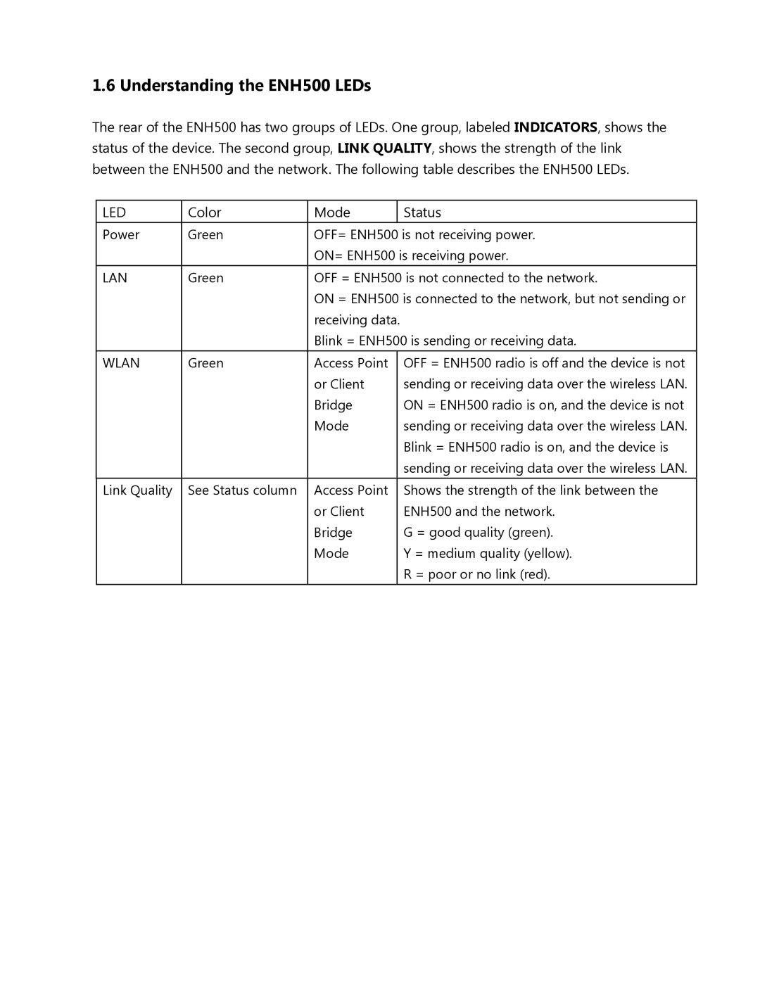
The rear of the ENH500 has two groups of LEDs. One group, labeled INDICATORS, shows the status of the device. The second group, LINK QUALITY, shows the strength of the link between the ENH500 and the network. The following table describes the ENH500 LEDs.
LED | Color | Mode |
| Status |
Power | Green | OFF= ENH500 is not receiving power. | ||
|
| ON= ENH500 is receiving power. | ||
|
|
| ||
LAN | Green | OFF = ENH500 is not connected to the network. | ||
|
| ON = ENH500 is connected to the network, but not sending or | ||
|
| receiving data. |
| |
|
| Blink = ENH500 is sending or receiving data. | ||
WLAN | Green | Access Point |
| OFF = ENH500 radio is off and the device is not |
|
| or Client |
| sending or receiving data over the wireless LAN. |
|
| Bridge |
| ON = ENH500 radio is on, and the device is not |
|
| Mode |
| sending or receiving data over the wireless LAN. |
|
|
|
| Blink = ENH500 radio is on, and the device is |
|
|
|
| sending or receiving data over the wireless LAN. |
|
|
|
|
|
Link Quality | See Status column | Access Point |
| Shows the strength of the link between the |
|
| or Client |
| ENH500 and the network. |
|
| Bridge |
| G = good quality (green). |
|
| Mode |
| Y = medium quality (yellow). |
|
|
|
| R = poor or no link (red). |
