The FN100 Chassis View
Viewing Chassis Information
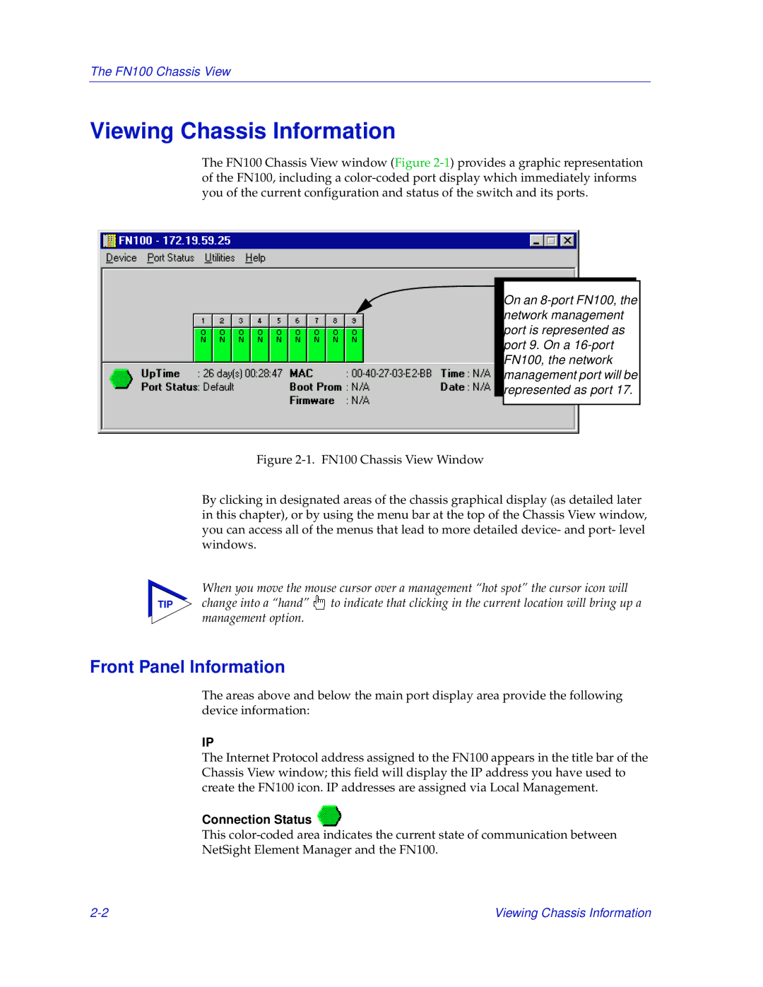
The FN100 Chassis View window (Figure
On an
Figure 2-1. FN100 Chassis View Window
By clicking in designated areas of the chassis graphical display (as detailed later in this chapter), or by using the menu bar at the top of the Chassis View window, you can access all of the menus that lead to more detailed device- and port- level windows.
When you move the mouse cursor over a management “hot spot” the cursor icon will
TIP change into a “hand” ![]() to indicate that clicking in the current location will bring up a management option.
to indicate that clicking in the current location will bring up a management option.
Front Panel Information
The areas above and below the main port display area provide the following device information:
IP
The Internet Protocol address assigned to the FN100 appears in the title bar of the Chassis View window; this field will display the IP address you have used to create the FN100 icon. IP addresses are assigned via Local Management.
Connection Status 
This
NetSight Element Manager and the FN100.
Viewing Chassis Information |