Features
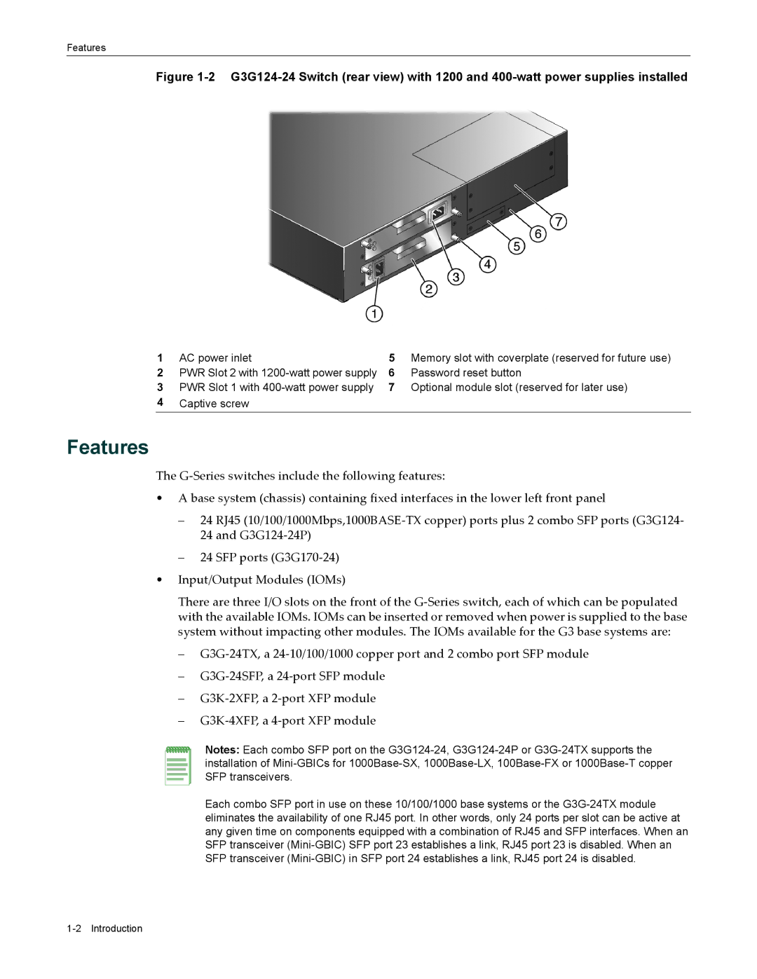
Figure 1-2 G3G124-24 Switch (rear view) with 1200 and 400-watt power supplies installed
1 | AC power inlet | 5 | Memory slot with coverplate (reserved for future use) |
2 | PWR Slot 2 with | 6 | Password reset button |
3 | PWR Slot 1 with | 7 | Optional module slot (reserved for later use) |
4Captive screw
Features
The G‐Series switches include the following features:
•A base system (chassis) containing fixed interfaces in the lower left front panel
–24 RJ45 (10/100/1000Mbps,1000BASE‐TX copper) ports plus 2 combo SFP ports (G3G124‐ 24 and G3G124‐24P)
–24 SFP ports (G3G170‐24)
•Input/Output Modules (IOMs)
There are three I/O slots on the front of the G‐Series switch, each of which can be populated with the available IOMs. IOMs can be inserted or removed when power is supplied to the base system without impacting other modules. The IOMs available for the G3 base systems are:
–G3G‐24TX, a 24‐10/100/1000 copper port and 2 combo port SFP module
–G3G‐24SFP, a 24‐port SFP module
–G3K‐2XFP, a 2‐port XFP module
–G3K‐4XFP, a 4‐port XFP module
Notes: Each combo SFP port on the
Each combo SFP port in use on these 10/100/1000 base systems or the