Enterasys Networks G3G124P-24, G3G170-24, G3G124-24 manual Tables

Models: G3G124-24 G3G124P-24 G3G170-24

1 70
Download 70 pages 46.57 Kb
Page 15
Image 15

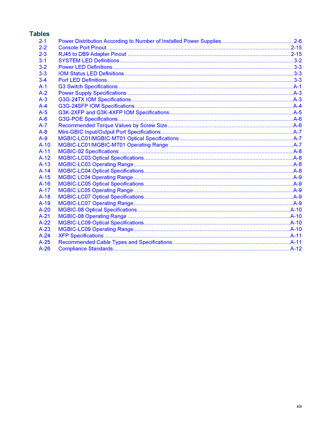
Tables

2-1

Power Distribution According to Number of Installed Power Supplies

............................................... 2-6

2-2

Console Port Pinout

2-15

2-3

RJ45 to DB9 Adapter Pinout

2-15

3-1

SYSTEM LED Definitions

3-2

3-2

Power LED Definitions

3-3

3-3

IOM Status LED Definitions

3-3

3-4

Port LED Definitions

3-3

A-1

G3 Switch Specifications

A-1

A-2

Power Supply Specifications

A-3

A-3

G3G-24TX IOM Specifications

A-3

A-4

G3G-24SFP IOM Specifications

A-4

A-5

G3K-2XFP and G3K-4XFP IOM Specifications

A-5

A-6

G3G-POE Specifications

A-6

A-7

Recommended Torque Values by Screw Size

A-6

A-8

Mini-GBIC Input/Output Port Specifications

A-7

A-9

MGBIC-LC01/MGBIC-MT01 Optical Specifications

A-7

A-10

MGBIC-LC01/MGBIC-MT01 Operating Range

A-7

A-11

MGBIC-02 Specifications

A-8

A-12

MGBIC-LC03 Optical Specifications

A-8

A-13

MGBIC-LC03 Operating Range

A-8

A-14

MGBIC-LC04 Optical Specifications

A-8

A-15

MGBIC LC04 Operating Range

A-9

A-16

MGBIC-LC05 Optical Specifications

A-9

A-17

MGBIC LC05 Operating Range

A-9

A-18

MGBIC-LC07 Optical Specifications

A-9

A-19

MGBIC-LC07 Operating Range

A-9

A-20

MGBIC-08 Optical Specifications

A-10

A-21

MGBIC-08 Operating Range

A-10

A-22

MGBIC-LC09 Optical Specifications

A-10

A-23

MGBIC-LC09 Operating Range

A-10

A-24

XFP Specifications

A-11

A-25

Recommended Cable Types and Specifications

A-11

A-26

Compliance Standards

A-12

xiii

Page 15
Image 15
Enterasys Networks G3G124P-24, G3G170-24, G3G124-24 manual Tables