Connecting to the Network
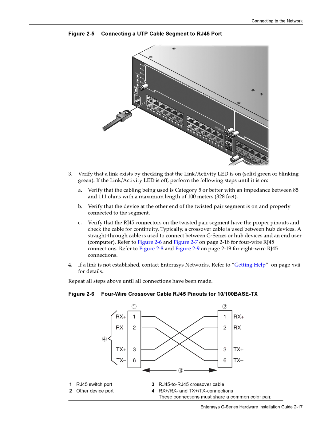
Figure 2-5 Connecting a UTP Cable Segment to RJ45 Port
3.Verify that a link exists by checking that the Link/Activity LED is on (solid green or blinking green). If the Link/Activity LED is off, perform the following steps until it is on:
a.Verify that the cabling being used is Category 5 or better with an impedance between 85 and 111 ohms with a maximum length of 100 meters (328 feet).
b.Verify that the device at the other end of the twisted pair segment is on and properly connected to the segment.
c.Verify that the RJ45 connectors on the twisted pair segment have the proper pinouts and check the cable for continuity. Typically, a crossover cable is used between hub devices. A straight‐through cable is used to connect between G‐Series or hub devices and an end user (computer). Refer to Figure 2‐6 and Figure 2‐7 on page 2‐18 for four‐wire RJ45 connections. Refer to Figure 2‐8 and Figure 2‐9 on page 2‐19 for eight‐wire RJ45 connections.
4.If a link is not established, contact Enterasys Networks. Refer to “Getting Help” on page xvii for details.
Repeat all steps above until all connections have been made.
Figure 2-6 Four-Wire Crossover Cable RJ45 Pinouts for 10/100BASE-TX
| À |
|
|
RX+ | 1 |
RX– | 2 |
à |
|
TX+ | 3 |
TX– | 6 |
|
|
Â
Á
1RX+
2 RX–
3TX+
6TX–
1 | RJ45 switch port | 3 | |
2 | Other device port | 4 | RX+/RX- and |
|
|
| These connections must share a common color pair. |
Enterasys