Installing an Optional PoE Module in the
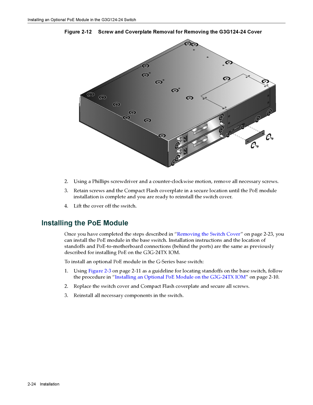
Figure 2-12 Screw and Coverplate Removal for Removing the G3G124-24 Cover
2.Using a Phillips screwdriver and a counter‐clockwise motion, remove all necessary screws.
3.Retain screws and the Compact Flash coverplate in a secure location until the PoE module installation is complete and you are ready to reinstall the switch cover.
4.Lift the cover off the switch.
Installing the PoE Module
Once you have completed the steps described in “Removing the Switch Cover” on page 2‐23, you can install the PoE module in the base switch. Installation instructions and the location of standoffs and PoE‐to‐motherboard connections (behind the ports) are the same as previously described for installing PoE on the G3G‐24TX IOM.
To install an optional PoE module in the G‐Series base switch:
1.Using Figure 2‐3 on page 2‐11 as a guideline for locating standoffs on the base switch, follow the procedure in “Installing an Optional PoE Module on the G3G‐24TX IOM” on page 2‐10.
2.Replace the switch cover and Compact Flash coverplate and secure all screws.
3.Reinstall all necessary components in the switch.