Inputs and Outputs
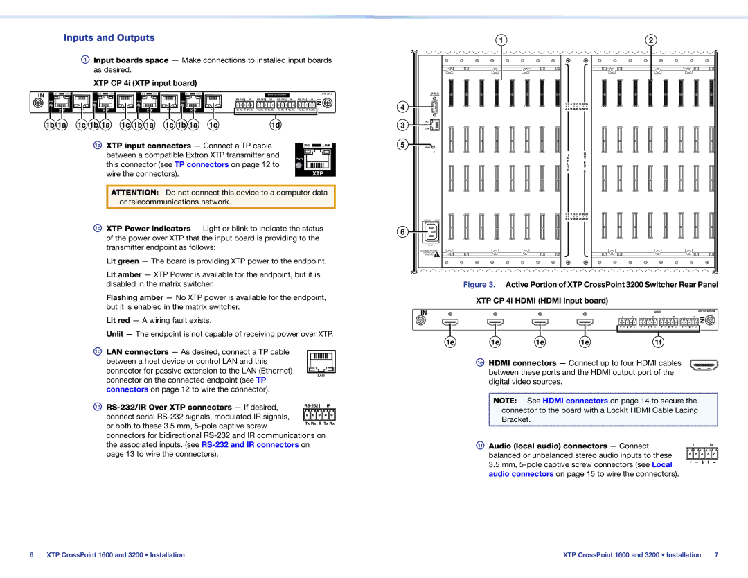
AInput boards space — Make connections to installed input boards as desired.
XTP CP 4i (XTP input board)
IN | SIG | LINK | SIG | LINK | SIG | LINK | SIG | LINK |
|
|
|
|
|
|
| XTP CP 4i | ||
| PWR |
| PWR |
| PWR |
| PWR |
|
| IR | IR | IR | IR | IN | ||||
|
|
|
|
|
|
|
|
|
|
|
|
|
| |||||
|
| XTP | LAN | XTP | LAN | XTP | LAN | XTP | LAN | Tx Rx | Tx Rx | Tx Rx | Tx Rx | Tx Rx | Tx Rx | Tx Rx | Tx Rx |
|
|
|
|
|
|
|
| ||||||||||||
| 1b 1a | 1c 1b 1a | 1c 1b 1a | 1c 1b 1a | 1c |
|
|
| 1d |
|
|
|
| |||||
1a XTP input connectors — Connect a TP cable | SIG |
| LINK | |||
| ||||||
between a compatible Extron XTP transmitter and |
|
|
|
|
|
|
PWR |
|
|
| |||
|
|
| ||||
this connector (see TP connectors on page 12 to |
|
|
| |||
|
|
|
|
|
| |
wire the connectors). |
|
|
| XTP | ||
ATTENTION: Do not connect this device to a computer data or telecommunications network.
1b XTP Power indicators — Light or blink to indicate the status of the power over XTP that the input board is providing to the transmitter endpoint as follows:
Lit green — The board is providing XTP power to the endpoint.
Lit amber — XTP Power is available for the endpoint, but it is disabled in the matrix switcher.
Flashing amber — No XTP power is available for the endpoint, but it is enabled in the matrix switcher.
Lit red — A wiring fault exists.
Unlit — The endpoint is not capable of receiving power over XTP.
1c LAN connectors — As desired, connect a TP cable between a host device or control LAN and this connector for passive extension to the LAN (Ethernet)
| 1 |
| 2 |
| REMOTE |
|
|
| RS 232/RS422 |
|
|
4 |
|
|
|
3 | ACT |
|
|
LAN |
|
| |
LINK |
|
| |
5 | RESET |
|
|
|
| I | O |
|
| U | |
|
| N | |
|
| T | |
|
| P | |
|
| P | |
|
| U | |
|
| U | |
|
| T | |
|
| T | |
|
| S | |
|
| S | |
|
|
| |
|
|
| |
6 |
|
|
|
|
|
| |
| DISCONNECT POWER |
|
|
| CORD BEFORE |
|
|
| SERVICING |
|
|
| Figure 3. | Active Portion of XTP CrossPoint 3200 Switcher Rear Panel | |
XTP CP 4i HDMI (HDMI input board)
IN | AUDIO | XTP CP 4i HDMI |
L | R | L | R | L | R | L | R | IN |
|
|
|
|
|
|
|
|
1e | 1e | 1e | 1e | 1f |
1e HDMI connectors — Connect up to four HDMI cables between these ports and the HDMI output port of the
connector on the connected endpoint (see TP connectors on page 12 to wire the connector).
LAN
digital video sources.
1d ![]() connect serial
connect serial ![]()
![]()
![]()
![]()
![]() or both to these 3.5 mm,
or both to these 3.5 mm, ![]() connectors for bidirectional
connectors for bidirectional
NOTE: See HDMI connectors on page 14 to secure the |
connector to the board with a LockIt HDMI Cable Lacing |
Bracket. |
1f Audio (local audio) connectors — Connect | L | R |
balanced or unbalanced stereo audio inputs to these |
|
|
3.5 mm, |
|
|
audio connectors on page 15 to wire the connectors). |
|
|
6 | XTP CrossPoint 1600 and 3200 • Installation | XTP CrossPoint 1600 and 3200 • Installation | 7 |