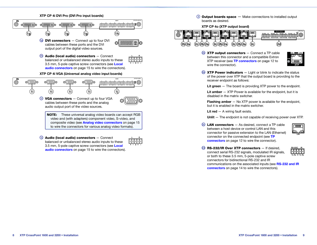
XTP CP 4i DVI Pro (DVI Pro input boards)
IN | AUDIO | XTP CP 4i DVI Pro |
L | R | L | R | L | R | L | R | IN |
|
|
|
|
|
|
|
|
1g | 1g | 1g | 1g | 1h |
1g DVI connectors — Connect up to four DVI cables between these ports and the DVI output port of the digital video sources.
1h | Audio (local audio) connectors — Connect | L | R |
|
| ||
| balanced or unbalanced stereo audio inputs to these |
|
|
| 3.5 mm, |
|
|
| audio connectors on page 15 to wire the connectors). |
|
|
XTP CP 4i VGA (Universal analog video input boards)
IN | AUDIO | XTP CP 4i VGA |
L | R | L | R | L | R | L | R | IN |
|
|
|
|
|
|
|
|
1i | 1i | 1i | 1i | 1j |
1i VGA connectors — Connect up to four VGA cables between these ports and the analog audio output port of the video sources.
NOTE: | These universal analog video boards can accept RGB |
video and (with adapters) component video, | |
composite video (see Analog video connectors on page 15 | |
to wire the connectors for various analog video formats). | |
1j | Audio (local audio) connectors — Connect | L | R |
|
| ||
| balanced or unbalanced stereo audio inputs to these |
|
|
| 3.5 mm, |
|
|
| audio connectors on page 15 to wire the connectors). |
|
|
OUT | SIG LINK |
| PWR |
XTP
2b 2a
BOutput boards space — Make connections to installed output boards as desired.
XTP CP 4o (XTP output board)
SIG | LINK | SIG | LINK | SIG | LINK |
|
|
|
|
|
|
| XTP CP 4o | ||
PWR |
| PWR |
| PWR |
|
| IR | IR | IR | IR | OUT | ||||
|
|
|
|
|
|
|
|
|
|
|
|
| |||
LAN | XTP | LAN | XTP | LAN | XTP | LAN | Tx Rx | Tx Rx | Tx Rx | Tx Rx | Tx Rx | Tx Rx | Tx Rx | Tx Rx |
|
|
|
|
|
| |||||||||||
2c 2b 2a | 2c 2b 2a | 2c 2b 2a | 2c |
|
|
| 2d |
|
|
|
| ||||
2a XTP output connectors — Connect a TP cable | SIG |
| LINK | |||
| ||||||
between this connector and a compatible Extron |
|
|
|
|
|
|
PWR |
|
|
| |||
|
|
| ||||
XTP receiver (see TP connectors on page 12 to |
|
|
| |||
|
|
|
|
|
| |
wire the connector). |
|
|
| XTP | ||
2b XTP Power indicators — Light or blink to indicate the status of the power over XTP that the output board is providing to the receiver endpoint as follows:
Lit green — The board is providing XTP power to the endpoint.
Lit amber — XTP Power is available for the endpoint, but it is disabled in the matrix switcher.
Flashing amber — No XTP power is available for the endpoint, but it is enabled in the matrix switcher.
Lit red — A wiring fault exists.
Unlit — The endpoint is not capable of receiving power over XTP.
2c LAN connectors — As desired, connect a TP cable between a host device or control LAN and this
connector for passive extension to the LAN (Ethernet) ![]()
![]() LAN
LAN ![]() connector on the connected endpoint (see TP
connector on the connected endpoint (see TP
connectors on page 12 to wire the connector).
2d | IR | |
|
| |
connect serial |
|
|
or both to these 3.5 mm, | Tx Rx | Tx Rx |
|
|
connectors for bidirectional
communications on the associated inputs (see
8 | XTP CrossPoint 1600 and 3200 • Installation | XTP CrossPoint 1600 and 3200 • Installation | 9 |