Installation
This section describes installation of the XTP CrossPoint matrix switchers, including connections and features. Topics that are covered include:
•• Rear Panel
•• Front Panel
Rear Panel
|
| 1−4 |
|
|
| INPUTS | 5−8 |
|
|
1 |
|
|
| |
|
| 9−12 |
|
|
3 |
| 13−16 |
|
|
| REMOTE | LAN |
| |
|
|
|
| |
4 |
|
|
| RESET |
|
|
|
| |
5 |
|
| LINK | ACT |
| 1−4 |
|
| |
|
|
|
| |
| OUTPUTS | 5−8 |
|
|
2 |
|
|
| |
|
| 9−12 |
|
|
6 |
| 13−16 |
|
|
|
|
| ||
|
|
| ||
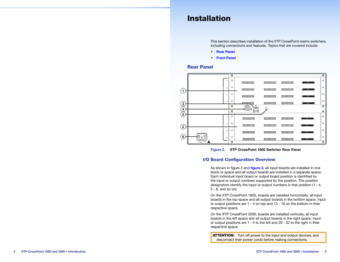
Figure 2. XTP CrossPoint 1600 Switcher Rear Panel
I/O Board Configuration Overview
As shown in figure 2 and figure 3, all input boards are installed in one block or space and all output boards are installed in a separate space. Each individual input board or output board position is identified by the input or output numbers supported by the position. The position designators identify the input or output numbers in that position (1 - 4, 5 - 8, and so on).
On the XTP CrossPoint 1600, boards are installed horizontally, all input boards in the top space and all output boards in the bottom space. Input or output positions are 1 - 4 on top and 13 - 16 on the bottom in their respective space.
On the XTP CrossPoint 3200, boards are installed vertically, all input boards in the left space and all output boards in the right space. Input or output positions are 1 - 4 to the left and 29 - 32 to the right in their respective space.
ATTENTION: Turn off power to the input and output devices, and disconnect their power cords before making connections.
4 | XTP CrossPoint 1600 and 3200 • Introduction | XTP CrossPoint 1600 and 3200 • Installation | 5 |