Installation and Operation, cont’d
Power
on
EXTRON DVS204D
2 sec.
NEXT
852x
480 @60
MENU
INPUT
CONFIG
MENU
OUTPUT
CONFIG
MENU
BLANKING
CONFIG
MENU
MEMORY
PRESET
MENU
ADVANCED
CONFIG
MENU
EXIT
MENU
2 sec.
MENU
2 sec.
INPUT 1
CMPOSITE
| 2 sec. |
| NO |
2 sec. | SIGNAL |
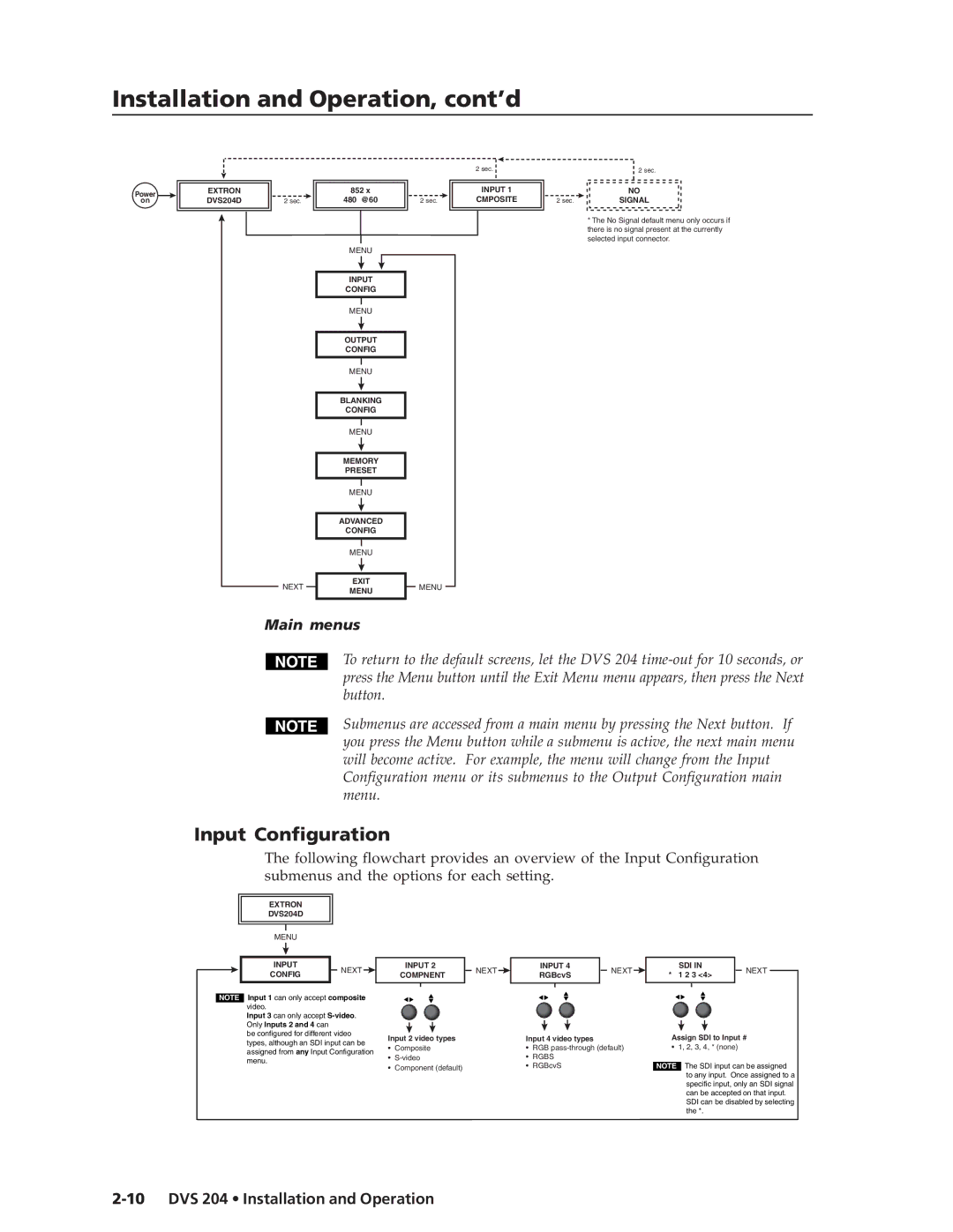
*The No Signal default menu only occurs if there is no signal present at the currently selected input connector.
Main menus
To return to the default screens, let the DVS 204
Submenus are accessed from a main menu by pressing the Next button. If you press the Menu button while a submenu is active, the next main menu will become active. For example, the menu will change from the Input Configuration menu or its submenus to the Output Configuration main menu.
Input Configuration
The following flowchart provides an overview of the Input Configuration submenus and the options for each setting.
EXTRON |
| |
DVS204D |
| |
MENU |
| |
INPUT | NEXT | |
CONFIG | ||
|
NOTE Input 1 can only accept composite video.
Input 3 can only accept
be configured for different video types, although an SDI input can be assigned from any Input Configuration menu.
INPUT 2 | NEXT | INPUT 4 | NEXT | SDI IN | NEXT | |
COMPNENT | RGBcvS | * 1 2 3 <4> | ||||
|
|
| ||||
Input 2 video types |
| Input 4 video types |
| Assign SDI to Input # | ||
• Composite |
| • RGB | • 1, 2, 3, 4, * (none) |
| ||
• |
| • RGBS |
| NOTE The SDI input can be assigned | ||
• Component (default) |
| • RGBcvS |
| |||
to any input. Once assigned to a specific input, only an SDI signal can be accepted on that input.
SDI can be disabled by selecting the *.
