Contents
DVS
Instrucciones de seguridad Español
Safety Instructions English
Consignes de Sécurité Français
Sicherheitsanleitungen Deutsch
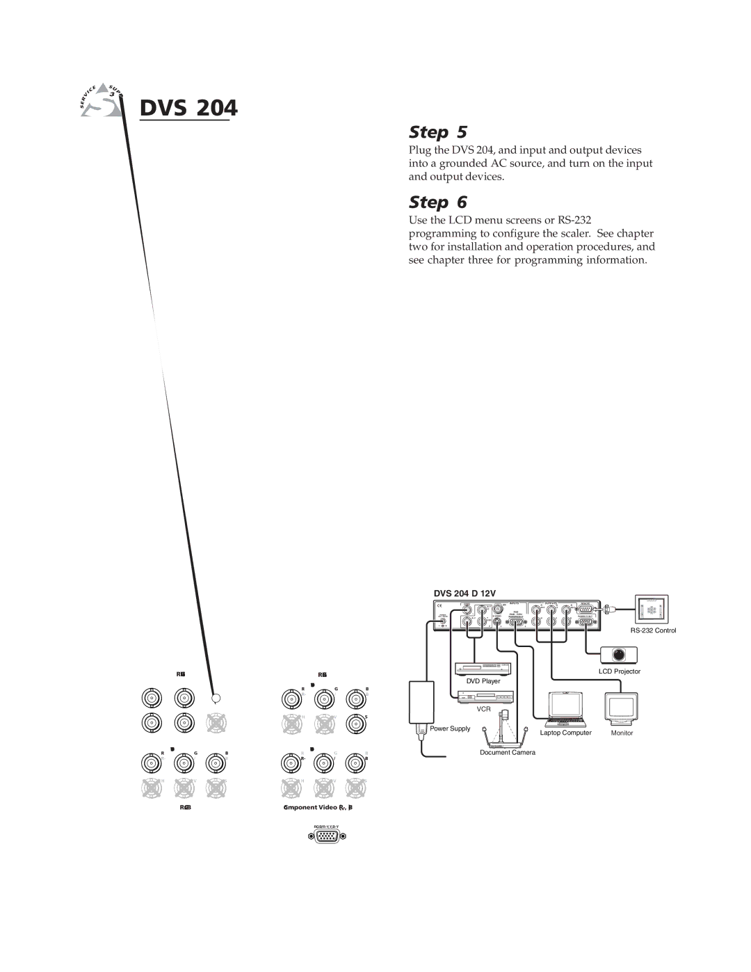
Application examples
Rear panel video inputs
Rear panel video outputs
Quick Start DVS 204, cont’d
Table of Contents
Table of Contents, cont’d
One
About this Manual
Features and Options
About the DVS
Options and accessories
Introduction, cont’d
Installation and Operation
Rack mounting
Tabletop/desktop placement
DVS 204 Installation and Operation
Mounting the Scaler
DVS
Application diagram
DVS 204 D rear panel connectors
Rear Panel Features
Outputs 7
Installation and Operation, cont’d
Picture adjustment buttons
Front Panel Features
Input selection buttons
Next button
Setting up a DVD source
Optimizing the System for a DVD
Menu button
Moving through menus by using front panel controls
Menus, Configuration, and Adjustments
Menu overview
Signal
Input Configuration
SDI input SDI
Output Configuration
Input 2 Video Type
Input 4 Video Type
Output Signal
Resolution and refresh rates
Sync Polarity
Top and bottom blanking
Blanking Configuration
Memory Preset
Format
Clear CLR memory preset
Save Save memory preset
Detail control
Advanced Configuration
Recalling a preset
Filter mode
Pulldown detection PAL Film mode detect submenu
Blue mode
Autoswitch Autosw mode
Enhanced Enh mode
Exit Menu
Image Adjustments
Color, tint, brightness, contrast, centering, sizing
System Reset
Input Reset
Enable Executive Mode
Front Panel Security Lockout Executive Mode
IR 901 Infrared Remote Control
Operating problems
Troubleshooting
Installation and Operation, cont’d
Three
Scaler-initiated messages
Error responses
RS-232 Programmer’s Guide
Host-to-scaler communications
Symbol definitions
Using the command/response tables
Serial Communication, cont’d
Command Ascii Command Response Additional description
Horizontal shift
Freeze
Values
Command Ascii Command Response
Using the control program
Installing the software
Control Software for Windows
Using the help program
Serial Communication, cont’d
AAppendix
DVS 204 Appendix
Specifications
Control/remote decoder/scaler
Included parts
Part Numbers and Accessories
Accessories
Accessories Part number
Top
Firmware Upgrade Installation
U41
U17 U41 U38
SDI connector opening SDI card standoff
Serial Digital Interface SDI Card Installation
Pin socket on back of SDI card Pin connector on main board
FCC Class a Notice Extron’s Warranty
Extron Electronics, USA