GSS 100 specifications
Extron Electronics GSS 100 is a powerful yet compact audio signal distribution system designed to enhance the audio experience in various applications, from classrooms to corporate environments. Known for its reliability and performance, the GSS 100 serves as an essential component for signal management in modern AV systems.One of the main features of the GSS 100 is its capability to distribute audio signals to multiple outputs while maintaining high fidelity. With the ability to handle both balanced and unbalanced signals, the GSS 100 can adapt to various audio sources and systems. This flexibility makes it suitable for a wide range of applications, including live events, presentation venues, and educational institutions.
The GSS 100 utilizes Extron’s advanced audio processing technology, which includes built-in audio mixing, equalization, and signal routing capabilities. Users can easily manage audio levels and blend multiple audio sources to create a seamless listening experience. This is particularly beneficial in environments where sound quality is paramount, allowing for adjustments that optimize the auditory experience for the audience.
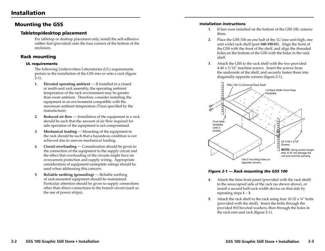
Another characteristic that sets the GSS 100 apart is its intuitive user interface. The device features a straightforward control system, making it easy for users to manage and configure settings without extensive technical knowledge. Additionally, the unit is built for quick installation, with both rear and front panel connections for flexible installation options. This design consideration helps streamline setup time and minimizes disruption.
The GSS 100 also integrates seamlessly with other Extron and third-party products, enhancing its versatility in complex AV systems. With various input and output configurations, users can connect the GSS 100 to microphones, mixers, and amplifiers effortlessly. Its ability to connect to networked AV systems further extends its capabilities, enabling remote monitoring and control through software interfaces.
In conclusion, the Extron Electronics GSS 100 stands out as a premier audio signal distribution system that combines advanced technology with user-friendly features. Whether for educational purposes, corporate events, or live productions, the GSS 100 delivers reliable performance and exceptional audio quality, ensuring an optimal listening experience for any audience. As a result, it remains a popular choice among AV professionals seeking to elevate their systems with efficient and effective audio management solutions.

