Manuals
/
Falcon
/
Household Appliance
/
Stove
Falcon
U108610-07
installation instructions
Circuit Diagram, Description, Colour
Models:
U108610-07
1
36
40
40
Download
40 pages
28.4 Kb
33
34
35
36
37
38
39
40
Troubleshooting
Install
Circuit Diagram
Tips on Cooking with the Timer
Fixed Wiring
Warranty
Setting the Time of Day
Cleaning Your Cooker
Pressure Testing
Usable volume litres
Page 36
Image 36
Page 35
Page 37
Page 36
Image 36
Page 35
Page 37
Contents
Installation Instructions
User Guide
90 Dual Fuel
U108610-07
Contents
1. Before You Start
WARNING The appliance and its accessible parts
surfaces To avoid overheating, DO NOT install the cooker
nnDO NOT use a steam cleaner to clean the cooker
nnThis appliance is heavy so take care when moving it
Always keep combustible materials, e.g. curtains
and ammable liquids a safe distance away from your cooker
DO NOT store ammable materials in the storage
2. Cooker Overview
Hotplate Burners
A B C D
Fig.2-1
Wok Burner
Fig.2-3 Fig.2-4
Fig.2-5 Fig.2-6
Fig.2-7
DO NOT put it crossways - it will not t properly and
will be unstable DO NOT put it on any other burner - it is not
designed to t in any of the other pan supports Fig.2-12
Always leave space around the griddle for the gases
nnNever close the grill door when the grill is on
ArtNo.210-0001 Classic grill control
Fig.2-15
Fig.2-16
Setting the Time of Day
A B C D E F
Minute Minder
To Stop the Ovens Automatically
AUTO is Showing, But you Want to Reset to Manual Cooking
Key Lock
Fig.2-30Fig.2-31
Fig.2-32
Oven Shelves - Left-hand Main Oven
Oven Shelves - Right-hand Tall Oven
The Handyrack Main Oven
Fig.2-35
Tips on Cooking with the Timer
General Oven Tips
DO NOT use the timed oven if the adjoining oven is
already warm
4. Cooking Table
5. Cleaning Your Cooker
DO NOT mix dierent cleaning products - they may
The Single Ring Burners
The Wok Burner
‘Cook & Clean’ Panels
Before you remove any of the grill parts for cleaning
DO NOT use harsh abrasive cleaners or sharp metal
Do not use steel wool, oven cleaning pads, or any
Recommended Cleaning Method
Removing the Main Oven Linings
Hotplate
Part
6. Troubleshooting
Hotplate ignition or hotplate burners faulty
What cleaning materials are recommended for the cooker?
Never use caustic or abrasive cleaners as these will
Fig.6-1 Fig.6-2
Fig.6-3
Fig.6-4
An oven light is not working
7. Installation
If you Have a Problem
Out of Warranty
INSTALLATION
Installer’s Name Installer’s Company Installer’s Telephone Number
Read the instructions before installing or using this appliance
AS 5601 - ‘Gas Installations’
Failure to install the appliance correctly could
You will also need the following tools
Checking the Parts
1. Overhead - Measurement A
2. Side Clearances - Measurements B & C
3. Side Clearances - Measurement D & E
Fig.7-1
Lowering the Two Rear Rollers
Completing the Move
On no account try and move the cooker while it is
plugged into the electricity supply
Unless properly installed, the cooker could be tipped by
Fitting the Stability Bracket and Chain
Fitting a Stability Bracket
Fitting the Restraining Chain
Pressure Testing
Gas Connection
Natural Gas
Propane
Fixed Wiring
A N
Fig.7-10
Fig.7-11
Hotplate Check
Grill Check
Oven Check
Fitting the Handles and Handrail Classic only
8. Conversion to LP Gas
When servicing or replacing gas-carrying
Classic - Removing the Control Panel
Toledo - Removing the Control Panel
Fig.8-4
9. Servicing
1.1 To Remove the Control Panel
1.2 To Remove the Side Panels
WARNING - SERVICING TO BE CARRIED OUT ONLY BY AN AUTHORISED PERSON
2.1 To Remove the Hotplate
2.2 To Replace the Hotplate Control Taps
2.3 To Change a Hotplate Burner Injector
2.4 To Replace a Hotplate Burner Electrode
3.1. To Replace the Ignition or Light Switch
3.2 To Replace the Clock
3.3 To Change the Ignition Generator
4.1 To Replace the Grill Controller
5.3 To Change the Oven Element
5.4 To Change an Oven Element Thermal Cut-out
5.5 To Replace an Oven Thermostat
Fig.9-4 Fig.9-5
6.3 To Adjust the Main Oven Door Angle
6.6 To Adjust the Main Oven Door Catch Keep
6.1 To Remove the Grill Door
6.2 To Replace the Main Oven Door
6.7 To Remove the Tall Oven Door
6.8 To Replace the Tall Oven Door Outer Panel
6.9 To Replace the Tall Oven Door Magnetic Latch
6.10 To Change an Oven Door Seal
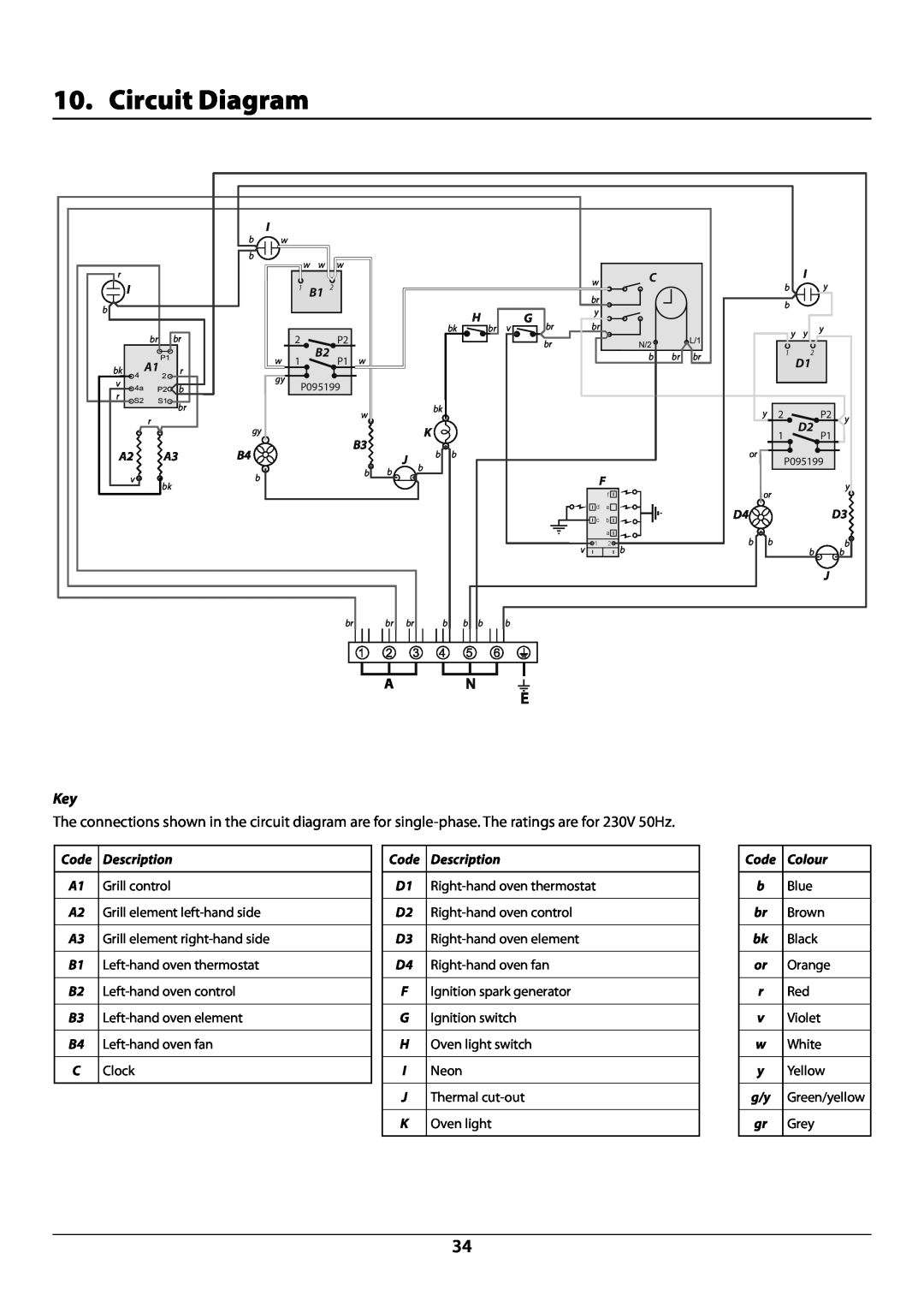
10. Circuit Diagram
Description
Colour
11. Technical Data
Maximum power output @ 230V 50 Hz
Usable volume litres
COUNTRY OF DESTINATION Australia
Page
Page
Clarence Street, Royal Leamington Spa Warwickshire, CV31 2AD, England
Tel +44 0 1926 457400 Fax +44 0 1926
E-mail consumers@falconappliances.co.uk
Top
Page
Image
Contents