Version
Page
Table of Contents
Diagnostics
Group 3 error flowchart no paper in ADF paper tray
Page
General
General
System Block Diagram
Device Configuration
Outer View
Components
Functional Specifications
Functional Specifications Remarks
Environmental Specifications
Environmental Specifications Remarks
Operation
Removing the Shipping Bracket
Remove the shipping retainer Fasten the shipping retainer
Power On/Off
Indication Panel
Setting the Scsi ID and Connecting the Interface Cable
Names and functions of the indicators
Scsi ID setting
Name Color Function
Scsi Cable Connection
Position
Paper Specifications
Paper Size
Paper conditions
2.1 ADF
FIatbed
Items to avoid
Readable area
ADF readable area
Document Setting Method
When the document size is of letter/A4 size or smaller
Flatbed
When the document is a thick book
Setting the ADF paper chute
2 ADF
Placing the documents on the ADF paper chute
Placing the document on the ADF paper chute
Angling the document sheets
Separating the sheets for easy feeding
Cleaning
Cleaning the document cover and the document glass
Cleaning inside the ADF
Page
Interface
∙ Busy ∙ Check Condition ∙ Good ∙ Reservation Conflict
Physical Specifications
Connection
Physical Specification
Specifications
1SCSI physical specifications
Termination
Signal Name Pin Number
Pin assignments
System configuration
System configuration
Scsi Bus
Addresses of Scsi devices
Bus signals
2Bus signals
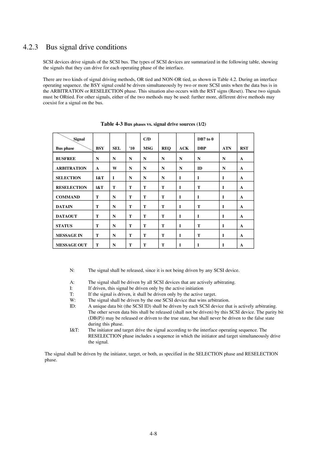
Bus signal drive conditions
3Bus phases vs. signal drive sources 1/2
Bus Phases
Method of driving the interface signal
Or connection Nonor connection
5Signal delay times definition Time Definition
BUS Free phase
Signal delay times definition
Time Definition
Arbitration phase
BSY Scsi SEL
Selection phase
Information Transfer phases
Information Transfer phase type Phase
DB7 to 9,P Transfer Direction
Asynchronous information transfer
Asynchronous transfer from target to initiator
Asynchronous transler from initiator to target
Commands
Relative addressing is not supported
Control byte is not supported
Reserve Unit command
Commands
Operation Command Code hex Description
Bit and field described as Reserved are
Reserve Unit command Command phase initiator Õ target
TP third party Byte
Tpid third party device ID Byte
Release Unit command
Release Unit command Command phase initiator → target
TP third party Byte
Inquiry command
Inquiry command Command phase initiator → target
10 Inquiry command
Step Bus phase Initiator operation Target operation
Evpd enable vital product data Byte
Code Byte
CAllocation length Byte
Inquiry data Data in phase target → initiator
Aenc
SftRst Soft Reset Byte
ADF mode Byte 24, bit
Color mode Byte 24, bit 6 to
ISO version, Ecma version, Ansi approved version Byte
Request Sense command
Request Sense command Command phase initiator → target
11 Request Sense command
Sense data Data EN phase target → initiator
Error code Byte
Allocation length Byte
Valid Byte
ILI incorrect length indicator Byte
FM file mark Byte
EOM end of medium Byte
Sense key Byte
Send Diagnostic command
Command-specific information bytes Bytes 8 to B
Sense Additional Description
Sense code
Send Diagnostic command Command phase initiator → target
PF page format Byte
Slftst selftest Byte
Test Unit Ready command
Contents of self-test
Results of self-test
Test Unit Ready command Command phase initiator → target
Acknowledgment
SET Window command
SET Window command Command phase initiator → target
Window date Data OUT phase initiator → target
Transfer Length Bytes 6 to
Header
Window descriptor block
Y resolution XR, YR Bytes 2 to 3 and 4 to
Window identifier Byte
Auto Byte
Upper left X,YULX, ULY Bytes 6 to 9, a to D
Brightness Byte
Remarks
Bit per pixel Byte 1A
RIF reverse image format Byte 1D, bit
Bit ordering Bytes 1E to 1F
Halftone pattern Bytes lB to 1C lB reserved
Update of ScanPartner 600C OEM manual
7.4 B&W Scanning Vender unique parameters
Compression type, argument Bytes 20 to
18 Vender unique parameters byte 28 and later
Page
Color Scanning Vender unique parameters
19 Vendor unique parameters byte 28 and later
ADF Byte 2A, Bit
Source Byte 2A, Bit
Highlight value Byte 2B
Shadow value Byte 2C
Line width Byte 2D to 2E
Line count Byte 2F to
Object Position command
Object Position command Command phase initator → target
Position type Byte
Bit
Unload object
Load object
Count Bytes 2 to
Normal
Read command
Step Bus phase Initiator operation Target operation
ADF sequence
Read command Command phase initiator → target
Data type code Byte
Data type qualifier Bytes 4 to
Transfer length TL Bytes 6 to
Data in phase target → initiator
Image data Data Type Code =
For binary data
Pixel size data Data Type Code =
Scan command
Scan Command phase initiator → target
Status Status phase target initiator
Code Status of unit
Phase ATN detection timing
Messages
ATN detection
Command Complete X00 Message in phase target → initiator
Message types
Message
Abort X06 Message OUT phase initiator → target
Message Reject X07 Message IN/OUT phase initiator → target
ATN detection phase Action
No Operation X08 Message OUT phase initiator → target
BUS Device Reset X0C Message OUT phase initiator → target
Phase when ATN is detected Action
Message rejected Action
Idendify X80 to XFF Message OUT phase initiator → target
Command Sequence
Initial sequence
Read command sequence
Read sequence for B&W mode
Read sequence
Single Read
Multiple Read
Status Transition of Logical Unit
Error Table
Sense key
Items for Specifying Window
Page
Online diagnostics
Ready LED Paper Jam LED Error indication
Online diagnostics
Offline diagnostics
Offline diagnostics results
Diagnostic flowcharts
Group 1 error flowchart Lamp assembly
Group 2 error flowchart Flatbed/ADF motor
Group 3 error flowchart paper in ADF paper tray
Group 3 error flowchart no paper in ADF paper tray