Back
00014791603
Safety Instructions
Table of Contents
Equipment Lists
Optional supply
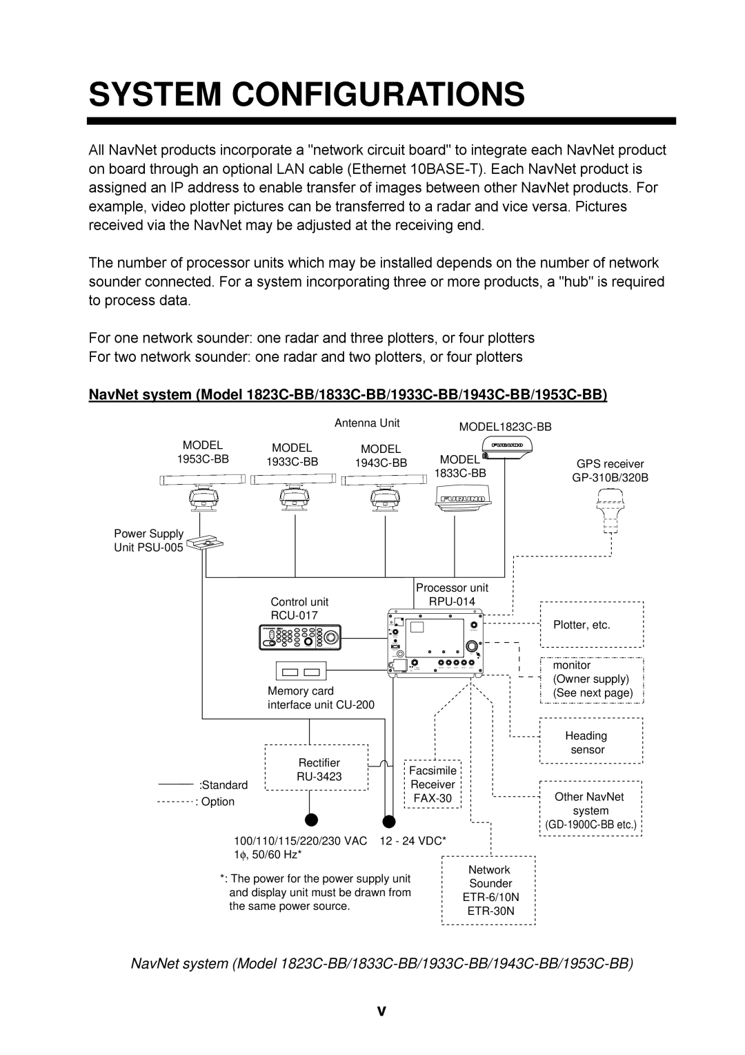
System Configurations
Single-unit NavNet system GD-1900C-BB
Single-unit NavNet system GD-1900C-BB
Three-or-more-unit NavNet system
Three-or-more-unit NavNet system
Two-unit NavNet system
Two-unit NavNet system
Mounting
Flush mounting of display unit
Flush mounting
Desktop mounting of display unit
Desktop mounting
Mounting the Processor Unit
Processor unit, mounting dimensions
Mounting the Antenna Unit of MODEL1823C-BB
Typical antenna unit placement on sailboat and powerboat
Antenna unit, showing location of mounting hardware
How to fasten the mounting base to platform
Antenna unit, inside view
Snap holder Remove and discard the packing material
GND
Location of EMI core
Sectional view
EMI core, putting into core case
How to pass the rotation detector cable
Antenna unit, clamping the rotation detector cable
Mounting the optional mounting bracket
How to assemble and mount the optional mounting bracket
Antenna unit
Mounting the Antenna Unit of MODEL1833C-BB
Antenna unit, inside view
How to fasten the radome base to the mounting platform
Wiring and final preparation
Antenna unit, cover removed
RF unit
Signal cable, antenna unit side
How to position the radome cover
How to attach EMI core
Mounting bracket contents
Mounting the Antenna Unit of MODEL1933C-BB/1943C-BB/1953C-BB
Coating the antenna with silicone sealant
Fastening the radiator to the radiator bracket
Fastening the radiator bracket to the antenna unit chassis
Antenna unit
Location of rubber mat
Fixing the antenna unit chassis
How to fasten antenna unit to mounting platform
Ground
Antenna unit chassis, upper chassis separated
Using inside fixing holes of the antenna housing
Antenna unit chassis, cover opened
Passing the signal cable through the cable gland assembly
How to fix signal cable in cable gland
Torque 9.8 ±0.1 N .m
Power supply unit
Mounting the Power Supply Unit of MODEL1953C-BB
Desktop mount
Mounting the Memory Card Interface Unit
Standard Wiring
Wiring
DJ-1
Waterproofing cap and connector nut, sectional view
Connecting GP-310B/320B to Data 2 port
Connecting GP-310B/320B to Data 2 port
Power supply unit, cover removed
Wiring of Power Supply Unit MODEL1953C-BB only
Replacement of the fuse
HUB
Connection of CU-200
How to access the Installation menu
How to Access the Installation Menu
Installation setup menu
Network setup menu
Network Setup Menu
Host name window
NavNet equipment default settings
Contents of Network setup menu
Radar setup menu
Radar Setup Menu
Antenna Type
Power supply unit, cover removed
Examples of improper and correct sweep timing
Tuning setup menu
Timing adjustment setting display
Timing adjust setting menu
Video adjustment setting window
Heading adjustment setting display
Heading Adjustment
Radar antenna height setting window
Main bung suppression setting window
Heading data setting window
STC curve setting window
Checking Magnetron Heater Voltage
Nav setup menu
Navigation Data Source
Position Source Furuno BB GPS ALL
Antenna height window
GPS setup menu
On next
Contents of GPS sensor settings menu
Contents of GPS sensor settings menu con’t
DATA1, DATA2 Port menus
Setting up Data Ports
Nmea data sentences
Contents of Data 1 and DATA2 Port menus
Remote System Setting
External buzzer
External Buzzer Connection
Processor unit cover removed
Name Type Code No Qty
ARP-11 contents
ARP Kit ARP-11
Necessary parts
19P1001 board J112
This page is intentionally left blank
Model 1823C-BB Model 1833C-BB
Page
Page
M1933C-BB/1943C-BB
Page
Page
Packing List
付属品表
PSU-005
CU-200-NAVBB
工事材料表
CU-200 Desktop mount kit
Page
Hatai
Page
Page
Page
Page
Page
Hatai
Page
Page
船舶用レーダー
Interconnection Diagram
Hatai
Marine Radar