g
Digital Energy™ LP Series
3.4Automatic Bypass Switch
If the output converter is unable to deliver the demanded output power because of overload or overtemperature, the automatic bypass switch will automatically transfer the load to the utility. When the situation is corrected the UPS will switch back to normal operation, i.e. the load is tranferred back to the output converter. Though the automatic bypass switch is shown as a simple mechanical switch in figures
In case of a severe overload or
|
|
|
| MANUAL BYPASS |
|
|
|
|
|
| SWITCH |
|
|
|
| BYPASS | STATIC |
|
|
|
|
| FILTER | BYPASS |
|
|
|
UTILITY INPUT |
|
|
|
| RFI | TO LOAD |
|
|
|
|
| FILTER | |
|
|
|
|
|
| |
|
| P.F. = 1 |
|
|
| OPTION |
RFI | BACKFEED | CONVERTER/ | OUTPUT |
|
| SLOTS FOR: |
FILTER | PROT. | RECTIFIER/ | CONVERTER |
|
| RPA CARD |
|
| BATTERY |
|
|
| |
|
| CHARGER |
| OUTPUT |
| SNMP CARD |
|
|
|
|
| ||
|
|
|
| TRANSFORMER |
| |
|
|
|
|
|
| |
| OPTIONAL |
|
|
|
| RELAY CARD |
|
|
|
|
|
| |
|
|
| SYSTEM | FRONT |
| STANDARD |
|
| BATTERY | PANEL |
| INSTALLED: | |
|
| ON/OFF |
| |||
|
|
|
|
| ||
| BATTERY |
|
|
|
| RS232/ |
|
|
|
|
| CONTACT | |
| EXTENSION |
|
|
|
| INTERFACE |
MICROPROCESSOR CONTROL
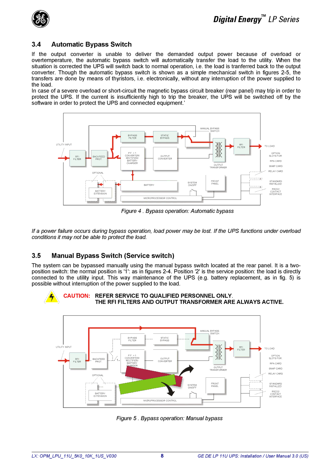
Figure 4 . Bypass operation: Automatic bypass
If a power failure occurs during bypass operation, load power may be lost. If the UPS functions under overload conditions it may not be able to protect the load.
3.5Manual Bypass Switch (Service switch)
The system can be bypassed manually using the manual bypass switch located at the rear panel. It is a two- position switch: the normal position is '1': as in figures
CAUTION: REFER SERVICE TO QUALIFIED PERSONNEL ONLY.
THE RFI FILTERS AND OUTPUT TRANSFORMER ARE ALWAYS ACTIVE.
|
|
|
| MANUAL BYPASS |
|
|
|
|
|
| SWITCH |
|
|
|
| BYPASS | STATIC |
|
|
|
|
| FILTER | BYPASS |
|
|
|
UTILITY INPUT |
|
|
|
| RFI | TO LOAD |
|
|
|
|
| FILTER | |
|
|
|
|
|
| |
|
| P.F. = 1 |
|
|
| OPTION |
RFI | BACKFEED | CONVERTER/ | OUTPUT |
|
| SLOTS FOR: |
FILTER | PROT. | RECTIFIER/ | CONVERTER |
|
| RPA CARD |
|
| BATTERY |
|
|
| |
|
| CHARGER |
| OUTPUT |
| SNMP CARD |
|
|
|
|
| ||
|
|
|
| TRANSFORMER |
| |
|
|
|
|
|
| |
| OPTIONAL |
|
|
|
| RELAY CARD |
|
|
|
|
|
| |
|
|
| SYSTEM | FRONT |
| STANDARD |
|
|
| PANEL |
| INSTALLED: | |
|
|
| ON/OFF |
| ||
|
|
|
|
|
| |
| BATTERY |
|
|
|
| RS232/ |
|
|
|
|
| CONTACT | |
| EXTENSION |
|
|
|
| INTERFACE |
|
|
| MICROPROCESSOR CONTROL |
|
|
|
Figure 5 . Bypass operation: Manual bypass
LX: OPM_LPU_11U_5K0_10K_1US_V030 | 8 | GE DE LP 11U UPS: Installation / User Manual 3.0 (US) |