g
Digital Energy™ LP Series
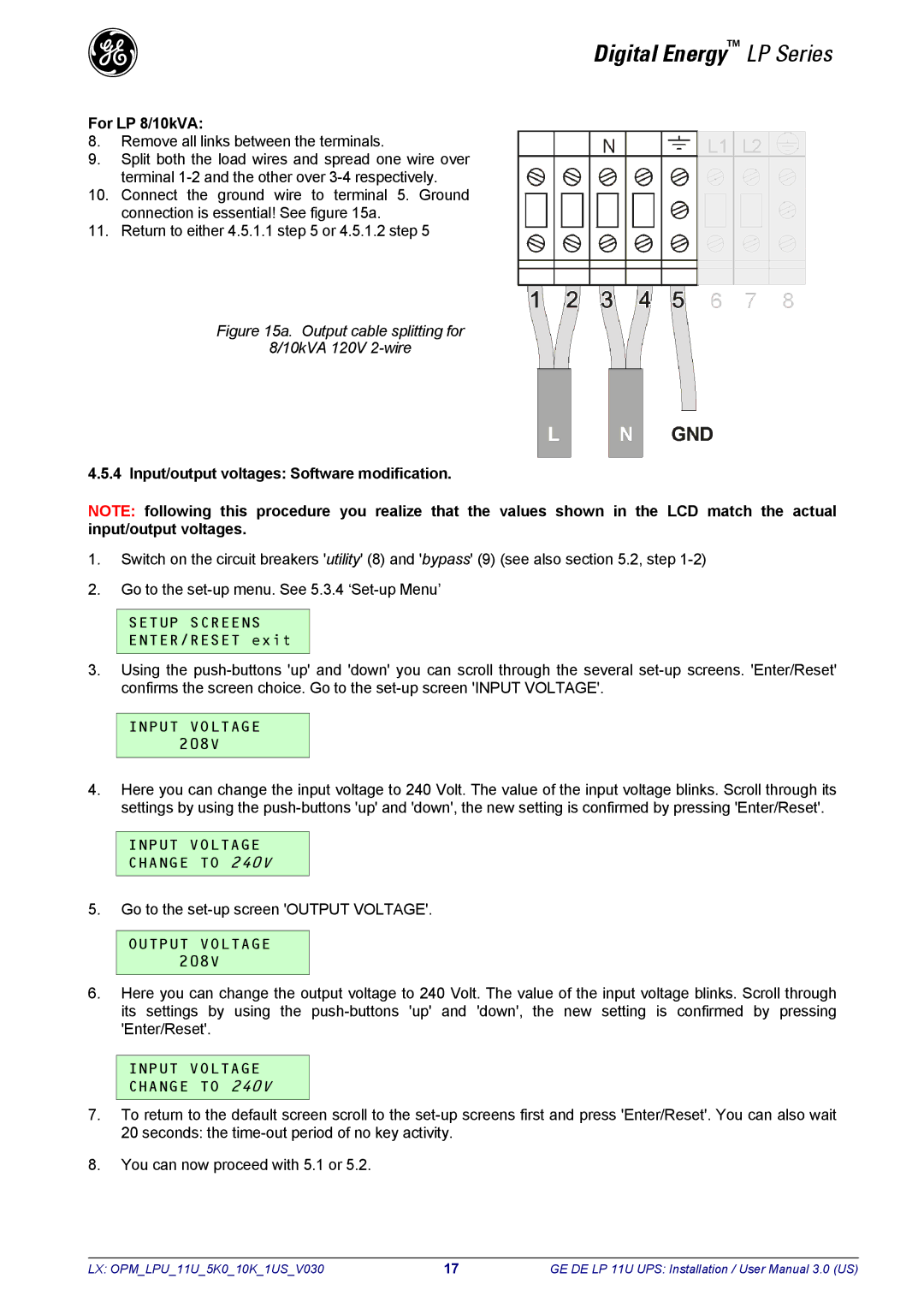
For LP 8/10kVA:
8.Remove all links between the terminals.
9.Split both the load wires and spread one wire over terminal
10.Connect the ground wire to terminal 5. Ground connection is essential! See figure 15a.
11.Return to either 4.5.1.1 step 5 or 4.5.1.2 step 5
Figure 15a. Output cable splitting for
8/10kVA 120V 2-wire
4.5.4 Input/output voltages: Software modification.
NOTE: following this procedure you realize that the values shown in the LCD match the actual input/output voltages.
1.Switch on the circuit breakers 'utility' (8) and 'bypass' (9) (see also section 5.2, step
2.Go to the
SETUP SCREENS
ENTER/RESET exit
3.Using the
INPUT VOLTAGE 208V
4.Here you can change the input voltage to 240 Volt. The value of the input voltage blinks. Scroll through its settings by using the
INPUT VOLTAGE
CHANGE TO 240V
5.Go to the
OUTPUT VOLTAGE
208V
6.Here you can change the output voltage to 240 Volt. The value of the input voltage blinks. Scroll through its settings by using the
INPUT VOLTAGE
CHANGE TO 240V
7.To return to the default screen scroll to the
8.You can now proceed with 5.1 or 5.2.
LX: OPM_LPU_11U_5K0_10K_1US_V030 | 17 | GE DE LP 11U UPS: Installation / User Manual 3.0 (US) |