g
Digital Energy™ LP Series
4.5.5Installation of GE Digital Energy™
Battery extension pack(s) are shipped with all materials necessary to connect them to the UPS. The pack(s) can be connected to the DC connector (15) at the rear panel of the UPS. Be sure to switch off the UPS before proceeding: be sure that the UPS can be switched off without causing damage to the load, and turn all circuit breakers
11a
2
3
4
5
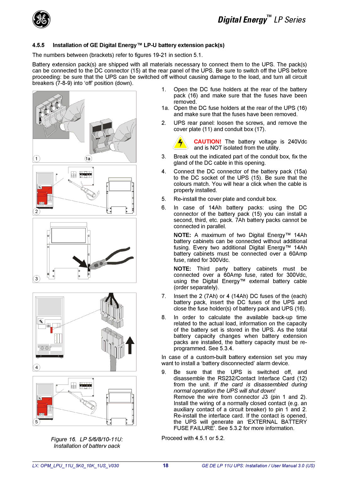
Figure 16. LP 5/6/8/10-11U: Installation of battery pack
1.Open the DC fuse holders at the rear of the battery pack (16) and make sure that the fuses have been removed.
1a. Open the DC fuse holders at the rear of the UPS (16) and make sure that the fuses have been removed.
2.UPS rear panel: loosen the screws, and remove the cover plate (11) and conduit box (17).
CAUTION! The battery voltage is 240Vdc and is NOT isolated from the utility.
3.Break out the indicated part of the conduit box, fix the gland of the DC cable in this opening.
4.Connect the DC connector of the battery pack (15a) to the DC socket of the UPS (15). Be sure that the colours match. You will hear a click when the cable is properly installed.
5.
6.In case of 14Ah battery packs: using the DC connector of the battery pack (15) you can install a second, third, etc. pack. 7Ah battery packs cannot be connected in parallel.
NOTE: A maximum of two Digital Energy™ 14Ah battery cabinets can be connected without additional fusing. Every two additional Digital Energy™ 14Ah battery cabinets must be connected over a 60Amp fuse, rated for 300Vdc.
NOTE: Third party battery cabinets must be connected over a 60Amp fuse, rated for 300Vdc, using the Digital Energy™ external battery cable (order separately).
7.Insert the 2 (7Ah) or 4 (14Ah) DC fuses of the (each) battery pack, insert the DC fuses of the UPS and close the fuse holder(s) of battery pack and UPS (16).
8.In order to calculate the available
In case of a
9.Be sure that the UPS is switched off, and disassemble the RS232/Contact Interface Card (12) from the unit. If the card is disassembled during normal operation the UPS will shut down!
Remove the wire from connector J3 (pin 1 and 2). Install the wiring of a normally closed contact (e.g. an auxiliary contact of a circuit breaker) to pin 1 and 2.
Proceed with 4.5.1 or 5.2.
LX: OPM_LPU_11U_5K0_10K_1US_V030 | 18 | GE DE LP 11U UPS: Installation / User Manual 3.0 (US) |