g
Digital Energy™ LP Series
5 - Operation
5.1Description of Front and Rear Panel
6 5 1 2 4 3
16 7 8 9
10
11a | 12a |
|
15 11
11b
17
18
14
13
12
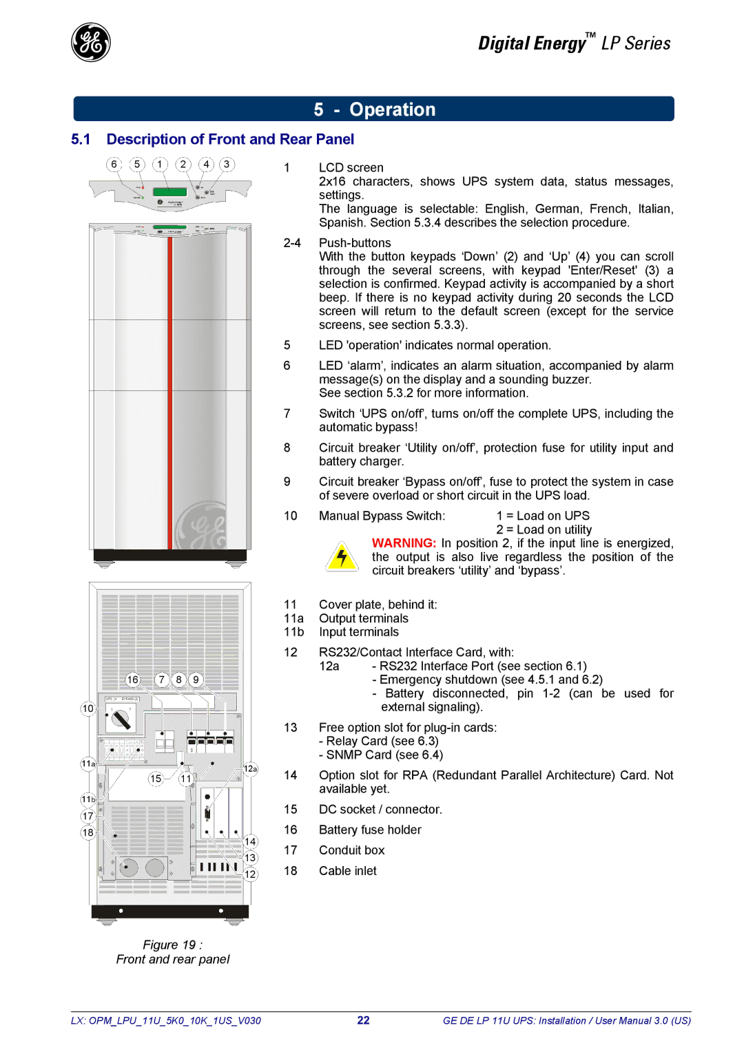
1LCD screen
2x16 characters, shows UPS system data, status messages, settings.
The language is selectable: English, German, French, Italian, Spanish. Section 5.3.4 describes the selection procedure.
With the button keypads ‘Down’ (2) and ‘Up’ (4) you can scroll through the several screens, with keypad 'Enter/Reset' (3) a selection is confirmed. Keypad activity is accompanied by a short beep. If there is no keypad activity during 20 seconds the LCD screen will return to the default screen (except for the service screens, see section 5.3.3).
5LED 'operation' indicates normal operation.
6LED ‘alarm’, indicates an alarm situation, accompanied by alarm message(s) on the display and a sounding buzzer.
See section 5.3.2 for more information.
7Switch ‘UPS on/off’, turns on/off the complete UPS, including the automatic bypass!
8Circuit breaker ‘Utility on/off’, protection fuse for utility input and battery charger.
9Circuit breaker ‘Bypass on/off’, fuse to protect the system in case of severe overload or short circuit in the UPS load.
10 Manual Bypass Switch: | 1 | = Load on UPS |
| 2 | = Load on utility |
WARNING: In position 2, if the input line is energized, the output is also live regardless the position of the circuit breakers ‘utility’ and ‘bypass’.
11Cover plate, behind it:
11a Output terminals
11b Input terminals
12RS232/Contact Interface Card, with:
12a - RS232 Interface Port (see section 6.1)
-Emergency shutdown (see 4.5.1 and 6.2)
-Battery disconnected, pin
13Free option slot for
-Relay Card (see 6.3)
-SNMP Card (see 6.4)
14Option slot for RPA (Redundant Parallel Architecture) Card. Not available yet.
15DC socket / connector.
16Battery fuse holder
17Conduit box
18Cable inlet
Figure 19 :
Front and rear panel
LX: OPM_LPU_11U_5K0_10K_1US_V030 | 22 | GE DE LP 11U UPS: Installation / User Manual 3.0 (US) |