Installation Preparation
CHECK INSTALLATION HARDWARE
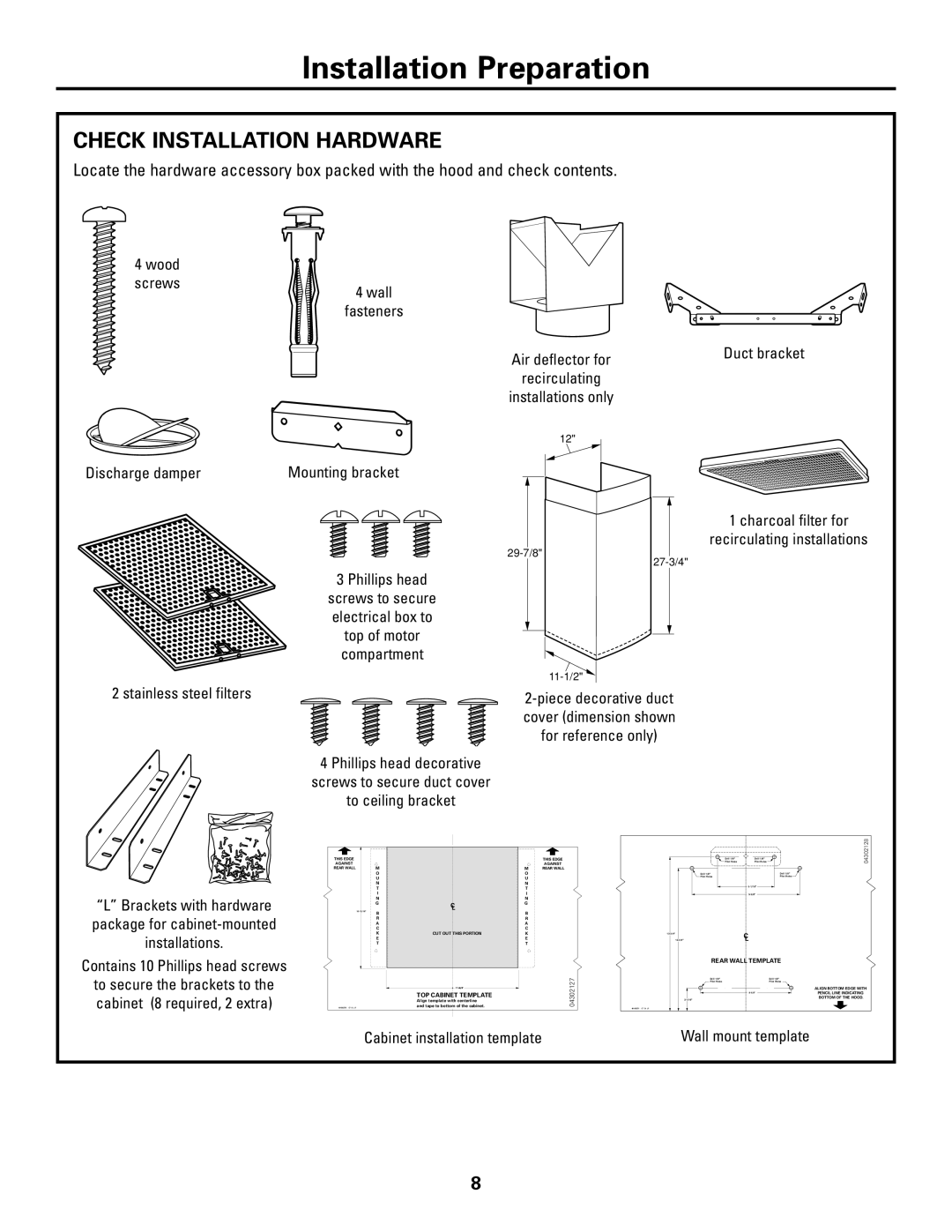
Locate the hardware accessory box packed with the hood and check contents.
4 wood
screws
4 wall fasteners
|
| Duct bracket | |
Air deflector for | |||
|
| ||
recirculating |
|
| |
|
| ||
installations only |
|
| |
|
|
|
12"
Discharge damper |
| Mounting bracket |
3 Phillips head
screws to secure electrical box to top of motor compartment
1 charcoal filter for
recirculating installations
2 stainless steel filters
4 Phillips head decorative
screws to secure duct cover
to ceiling bracket
“L” Brackets with hardware package for
Contains 10 Phillips head screws
to secure the brackets to the cabinet (8 required, 2 extra)
THIS EDGE |
|
AGAINST |
|
REAR WALL | M |
| O |
| U |
| N |
| T |
| I |
| N |
| G |
|
|
B
R
A
C
K
E
T
C
L
CUT OUT THIS PORTION
TOP CABINET TEMPLATE
Align template with centerline and tape to bottom of the cabinet.
THIS EDGE
AGAINST
MREAR WALL
O U N T I N G
B
R
A
C
K
E
T
04302127
|
|
|
|
|
|
|
|
| Drill 1/8" |
|
|
| Drill 1/8" | |||||||
|
|
|
|
|
|
|
|
| Pilot Holes |
|
|
| Pilot Holes |
|
|
|
| |||
|
|
|
|
|
|
|
|
|
|
|
|
|
|
|
|
|
|
|
|
|
|
|
|
|
|
|
|
|
|
|
|
|
|
|
|
|
|
|
|
| |
|
|
|
|
|
|
| Drill 1/8" |
|
|
|
|
|
|
|
| Drill 1/8" |
| |||
|
|
|
|
|
|
| Pilot Holes |
|
|
|
|
|
|
|
| Pilot Holes |
| |||
|
|
|
|
|
|
|
|
|
|
|
|
|
|
|
|
|
|
| ||
|
|
|
|
|
|
|
|
|
|
|
|
|
|
|
|
|
| |||
|
|
|
|
|
|
|
|
|
|
|
|
|
|
|
|
|
|
| ||
|
|
|
|
|
|
|
|
|
|
|
|
|
|
|
|
|
| |||
|
|
|
|
|
|
|
|
|
|
| C | |||||||||
|
|
|
|
|
|
|
|
|
| |||||||||||
|
|
|
|
|
|
|
| L | ||||||||||||
|
|
|
|
|
|
|
| REAR WALL TEMPLATE | ||||||||||||
|
|
|
|
|
|
|
| Drill 1/8" |
|
|
|
| Drill 1/8" | |||||||
|
|
|
|
|
|
|
| Pilot Holes |
|
|
|
| Pilot Holes | |||||||
|
|
|
|
|
|
|
|
|
|
|
|
|
|
|
|
|
|
|
| |
|
|
|
|
|
|
|
|
|
|
|
|
|
|
|
|
|
|
| ||
|
|
|
|
|
|
|
|
|
|
|
|
|
|
|
|
|
| |||
|
|
|
|
|
|
|
|
|
|
|
|
|
|
|
|
|
|
| ||
|
| 2- | 1/16" |
|
|
|
|
|
|
|
|
|
|
|
|
|
| |||
40 03 12 82
ALIGN BOTTOM EDGE WITH
PENCIL LINE INDICATING BOTTOM OF THE HOOD.
Cabinet installation template |
| Wall mount template |
|
|
|
8