G0516 specifications
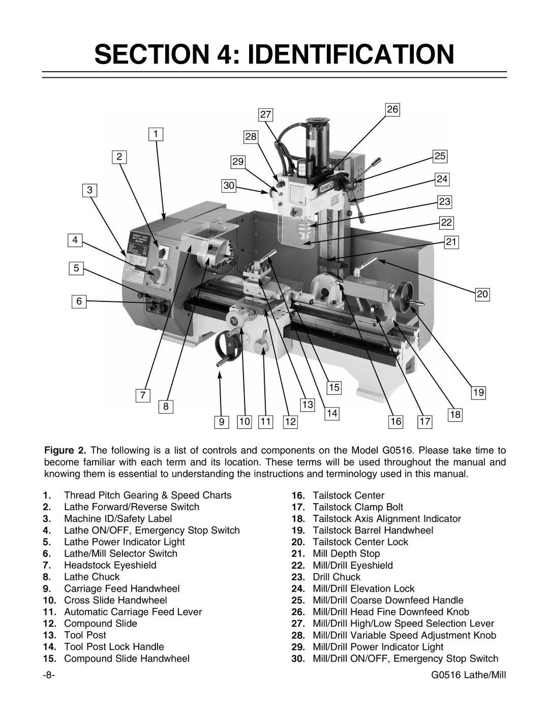
The Grizzly G0516 is a versatile and powerful combo machine that combines the functionality of a wood lathe and a 6" jointer, making it an ideal choice for woodworkers looking to save space in their workshops without compromising on capability. Engineered for versatility, this machine caters to both beginners and experienced craftsmen, featuring a robust build and a comprehensive array of features.One of the standout characteristics of the Grizzly G0516 is its solid construction. Built with a cast iron body, this machine provides stability and reduces vibration during operation, ensuring smooth performance. The lathe boasts a 12-inch swing and a 40-inch distance between centers, giving woodworkers the ability to turn larger projects with ease. The spindle is equipped with a 1-inch x 8 TPI thread, allowing for interchangeable accessories and enhancing the machine’s functionality.
The jointer aspect of the G0516 is equally impressive. It features a 6-inch cutting width and a 40-inch long bed, ensuring sufficient surface area for jointing edges of lumber. The 1 HP motor provides powerful performance, allowing for quick and efficient stock removal. The adjustable fence is another notable feature, enabling precise angle adjustments for various wood jointing scenarios.
In terms of technology, the Grizzly G0516 integrates modern advancements to enhance usability. The variable speed lathe function allows users to adjust the spindle speed, accommodating a wide range of wood types and turning techniques. Additionally, the machine includes a built-in dust port, promoting a cleaner working environment and improving airflow, which is particularly important when jointing.
Another important highlight is the user-friendly design, which features easy-access controls for both the lathe and jointer functions. Assembly and maintenance are made simpler with clear instructions, ideal for users who may be using such equipment for the first time. The compact design fits neatly in smaller workshops while offering a wide range of capabilities typically found in larger, standalone machines.
In conclusion, the Grizzly G0516 is a remarkable piece of machinery that combines the essential features of a wood lathe and jointer in a single, efficient unit. With its sturdy construction, modern technology, and user-friendly design, this machine is an invaluable tool for any woodworker aiming to maximize productivity while keeping their workspace organized. Whether you’re turning bowls, crafting furniture, or jointing edges, the G0516 rises to the occasion with precision and ease.

