5.While an assistant holds the extension table, fasten the 913/8" front rail to the extension table with three flat head screws, flat washers and hex nuts (Figure 13). Finger tighten for now.
Figure 13. Front rail/table fastener locations.
6.Fasten the 79" rear rail to the extension table with three cap screws, lock washers (out- side), flat washers, and hex nuts (inside), as shown in Figure 14. Finger tighten for now.
Figure 15. Aligning main extension table.
8.Repeat the aligning procedure and tighten the fasteners in Figure 14 with a 6mm hex wrench and 12mm wrench.
9.Using a 17mm wrench, tighten the hex bolts shown in Figure 12.
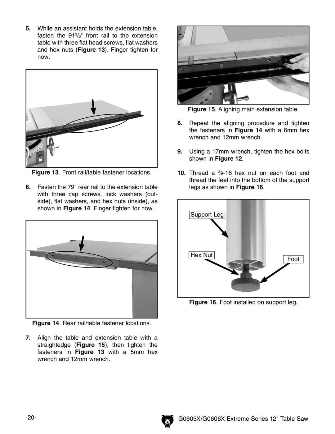
10.Thread a 3⁄8-16 hex nut on each foot and thread the feet into the bottom of the support legs as shown in Figure 16.
Support Leg
Hex Nut | Foot |
|
Figure 16. Foot installed on support leg.
Figure 14. Rear rail/table fastener locations.
7.Align the table and extension table with a straightedge (Figure 15), then tighten the fasteners in Figure 13 with a 5mm hex wrench and 12mm wrench.
G0605X/G0606X Extreme Series 12" Table Saw |