Manuals
/
Grizzly
/
Power Tools
/
Saw
Grizzly
G0700
owner manual
Hardware Recognition Chart
Models:
G0700
1
17
88
88
Download
88 pages
25.77 Kb
14
15
16
17
18
19
20
21
Troubleshooting
Install
Parts list
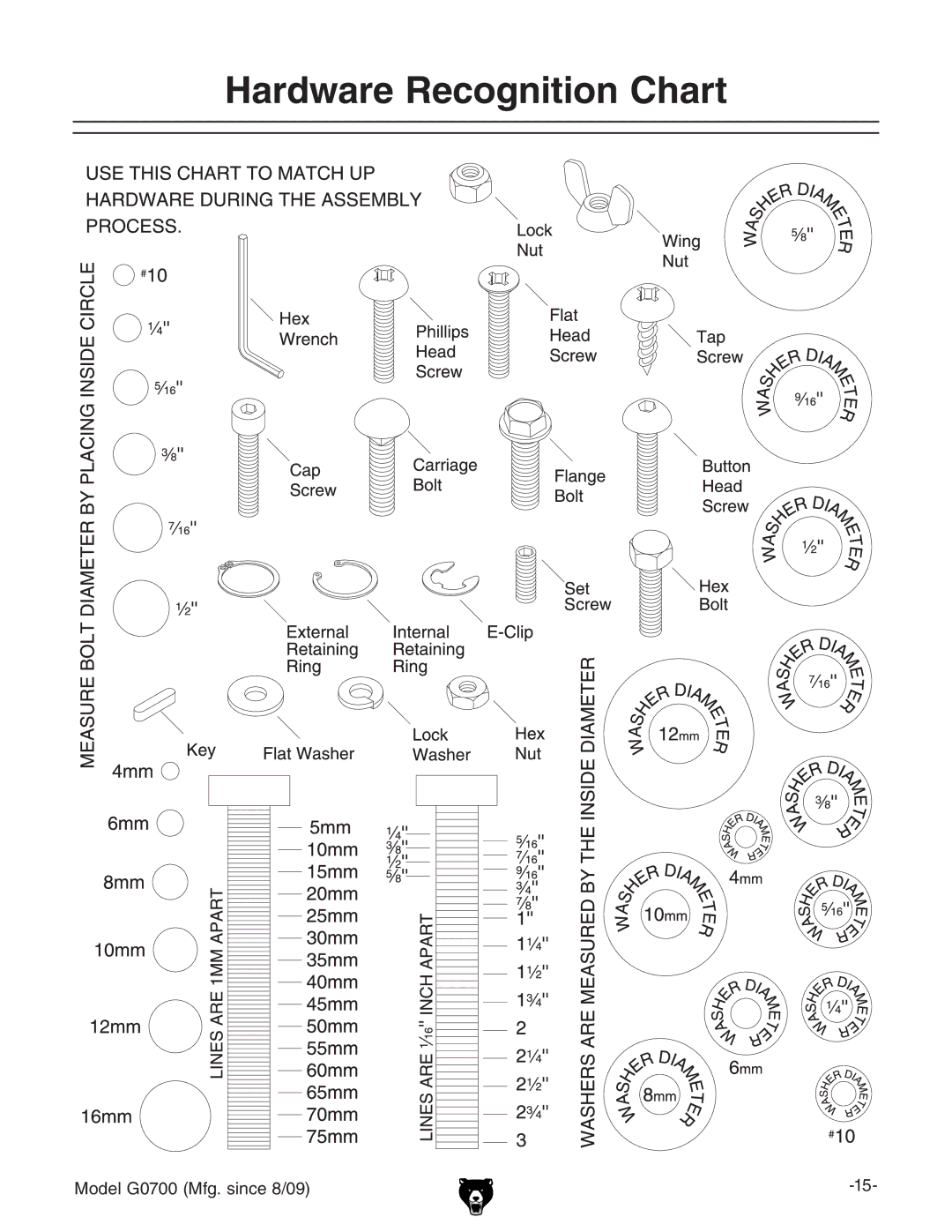
Hardware Recognition Chart
Machine Data Sheet
Wiring
Warranty
Maintenance
Belt Replacement
Setup
Page 17
Image 17
Hardware Recognition Chart
Model G0700 (Mfg. since 8/09)
-15-
Page 16
Page 18
Page 17
Image 17
Page 16
Page 18
Contents
Model G0700 Sliding Table SAW
Page
Table of Contents
Manual Accuracy
Introduction
Contact Info
Machine Description
Identification
Machine Data Sheet
Other Related Information
SlIdINg TABle SAW CAPACITIeS
Safety Instructions for Machinery
Safety
Unattended OPERATION. Never leave
Additional Safety for Sliding Table Saws
Below are ways to avoid the most common causes of kickback
Preventing Kickback
Protecting Yourself From Kickback
Glossary of Terms
Availability
Power Supply
Full-Load Current Rating
Circuit Requirements for
Extension Cords
Grounding Instructions
Minimum Gauge Size 10 AWG
50 ft
Setup Safety Unpacking
Setup
Items Needed For Setup
Description Qty
Hardware Recognition Chart
Inventory
Item Figure Qty Rip Fence Round Rail Assembly
Item Figure Qty Table Saw
Item Figure Qty
Fasteners Grouped by Usage Qty
Push Handle Assembly w/Lock
Before cleaning, gather the following
Cleanup
Site Considerations
To remove the saw from the pallet
Moving & Placing Table Saw
Mounting rip fence scale
Installing the rip fence Model G0700 Mfg. since 8/09
Installing main blade
Page
Hose support installed
Dust hoses attached Model G0700 Mfg. since 8/09
Power Connection
To test run the saw
Test Run
Operation Overview
Operations
Non-Through Through Cuts
Workpiece Inspection
Non-Through Cuts
Through Cuts
Blade Guard Riving Knife
Riving Knife Installation & Removal
Ripping Blade Features
Blade Guard Installation & Removal
Blade Requirements
Blade Selection
Dado Blades
Crosscut blade features Laminate blade features
Combination blade features
To change the main blade
Changing Main Blade
Changing Scoring Blade
Changing/Adjusting Scoring Blade
Adjusting Scoring Blade
Rip Cutting with Sliding Table
Rip Cutting
Rip Cutting with Rip Fence
To perform a crosscutting operation
Crosscutting
To perform a miter cut
Miter Cutting
Dado Blade
Installing Dado Blade
Dado Cutting
Cutting Dadoes with a Standard Blade
Cutting Dadoes with a Dado Blade
Finished Dado Cut
To use a standard saw blade to cut dadoes
Cut 2 Blade
Rabbet Cutting
Cutting Rabbets with a Standard Blade
Cutting Rabbets with a Dado Blade
Blade
To cut rabbets with the standard blade
Making Resaw Barrier
Resawing
Tools Needed Qty
Components Needed for Resaw Barrier
Components Needed for Resawing
Resawing Operations
Making a Featherboard
Shop Made Safety Accessories
Featherboards
Now, proceed to Mounting Featherboard in Miter Slot on
Assembling miter slot featherboard Components
Mounting Featherboard in Miter Slot
Mounting Featherboards w/Clamps
Push Sticks
Using a Push Stick
Making a Push Stick
⁄ 2 Grid
Making a Push Block
Using a Push Block
Push Blocks
Zero-Clearance Insert
Drilled Hole
Outfeed Table
Cutaway View
Making a Narrow-Rip Push Block for an Auxiliary Fence
Narrow-Rip Auxiliary Fence & Push Block
Ripping with push block Model G0700 Mfg. since 8/09
Using the Auxiliary Fence and Push Block
Blades
Aftermarket Accessories from Grizzly
T21382-Scoring Blade
G7315Z-Super Heavy-Duty Shop FOX Mobile Base
H8003-Hydraulic Lifting lbs
Eye protection assortment
Cleaning
Maintenance
Schedule
Unpainted Cast Iron
Lubrication
Troubleshooting
Service
Symptom Possible Cause Possible Solution
Motor & Electrical
Operation
Scoring Belt Replacement
Belt Replacement
Main Belt Replacement
Stop
Blade Tilt Calibration
To adjust the sliding table parallel with the main blade
Sliding Table Parallel Adjustment
To square the miter fence with the blade
Squaring Miter
Fence to Blade
To adjust the riving knife mount block
Adjusting Riving Knife Mounting Block
Wiring Safety Instructions
Wiring
220 VAC
Wiring Diagrams
Electrical Components
Power junction box wiring
Parts
Description
Cabinet Parts List
Handwheels
Main Motor
Main Motor Parts List
Blade Housing
Tables
Tables Parts List
Fence
Fence Parts List
Miter Gauge
Labels & Miscellaneous
Model G0700 Mfg. since 8/09
Comments
Warranty Card
BOX BELLINGHAM, WA
Grizzly INDUSTRIAL, INC
Warranty and Returns
Warranty and Returns
Order Hours a DAY
Top
Page
Image
Contents