Grizzly G0700 owner manual Zero-Clearance Insert

Models: G0700

1 88
Download 88 pages 25.77 Kb
Page 54
Image 54

Zero-Clearance

Insert

Azero-clearance insert can be made for the saw in about 30 minutes, and must be made of 34" furniture quality plywood or a hardwood. (We rec- ommend making at least 6–12 while you are going through the process, so you have plenty on hand for varying blade widths, heights, or angles.

Azero-clearance insert is required if you want to install a dado blade. When a dado blade is installed, the scoring blade and riving knife are removed—as neither will properly perform their intended function.

If you plan to use a standard blade with a zero- clearance insert, additional modifications will need to be made in order to install the scoring blade and riving knife.

If you must use this saw to cut the dimen-

sions of the zero-clearance insert you will

fabricate in these instructions, make sure

you DO NOT make any cuts while the

included table insert is removed. THIS IS

DANGEROUS. You must re-install the table

insert, reassemble all saw components, and

remove all tools before cutting.


Items Needed

Qty

Table Saw

1

Drill Press

1

Sander

1

Drill Bits 732" and 1332"

1 Each

Plywood/Hardwood Piece 14" x 1116" x 34"

1

Bandsaw or Jigsaw (Optional)

1

Clamp (Optional)

1

To make a zero-clearance table insert, do

these steps:


1.DISCONNECT SAW FROM POWER

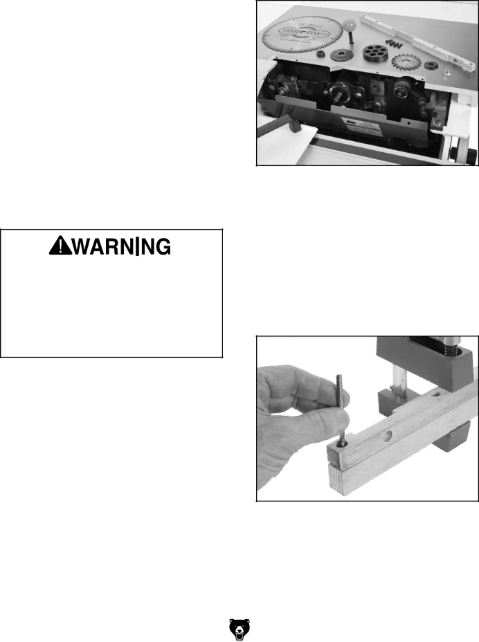
2.Lower the main blade all the way, remove the blade guard, riving knife, and scoring blade. After removing the scoring blade, reinstall and tighten the scoring blade flanges and arbor nut.

-52-

3.Remove the main blade and the spacer block behind it (see Figure 92).

Figure 92. Original table insert and all necessary

components removed.

4.Remove the table insert installed on the saw.

5.Cut the new table insert to the exact length of the included table insert and 1116" wide.

6.Use the included table insert as a template, as shown in Figure 93, to mark the mounting holes on the new table insert. (Clamping the pieces together while you do this will allow you to ensure the hole spacing is exact.)

Figure 93. Marking location for mounting holes

in new insert.

7.Use the 732" drill bit to drill holes completely through the new table insert.

8.Install the 1332" drill bit and use the included table insert as a guide to set the depth stop on your drill press to countersink the holes.

Model G0700 (Mfg. since 8/09)

Page 54
Image 54
Grizzly G0700 owner manual Zero-Clearance Insert