Reading the Charts
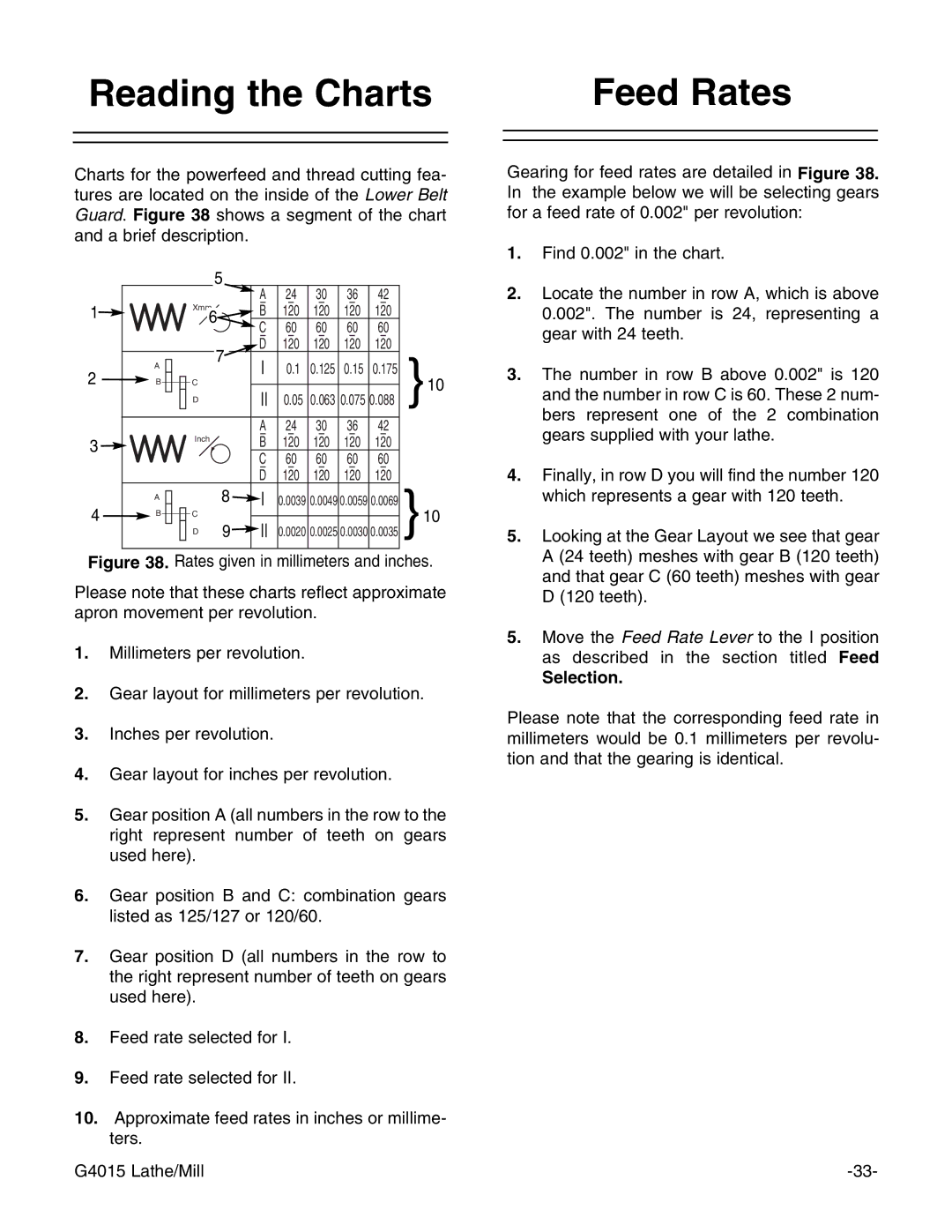
Charts for the powerfeed and thread cutting fea- tures are located on the inside of the Lower Belt Guard. Figure 38 shows a segment of the chart and a brief description.
|
|
| 5 | A | 24 | 30 | 36 | 42 |
|
|
|
|
|
| |||||
1 |
| Xmm6 | – | – | – | – | – |
| |
| B | 120 | 120 | 120 | 120 |
| |||
|
|
|
| C | 60 | 60 | 60 | 60 |
|
|
|
|
| – | – | – | – | – |
|
|
|
| 7 | D | 120 | 120 | 120 | 120 | }10 |
| A |
| I | 0.1 | 0.125 | 0.15 | 0.175 | ||
2 |
|
| |||||||
B | C |
| |||||||
|
|
|
|
|
| ||||
|
| D |
| II | 0.05 | 0.063 0.075 0.088 | |||
|
|
|
| A | 24 | 30 | 36 | 42 |
|
3 |
| Inch |
| – | – | – | – | – |
|
|
|
| B | 120 | 120 | 120 | 120 |
| |
|
|
|
| C | 60 | 60 | 60 | 60 |
|
|
|
|
| – | – | – | – | – |
|
|
|
|
| D | 120 | 120 | 120 | 120 |
|
| A |
| 8 | I | 0.0039 0.0049 0.0059 0.0069 |
| |||
|
|
|
| ||||||
4 | B | C |
|
| 0.0020 0.0025 0.0030 0.0035 }10 | ||||
| D | 9 | II | ||||||
Figure 38. Rates given in millimeters and inches.
Please note that these charts reflect approximate apron movement per revolution.
1.Millimeters per revolution.
2.Gear layout for millimeters per revolution.
3.Inches per revolution.
4.Gear layout for inches per revolution.
5.Gear position A (all numbers in the row to the right represent number of teeth on gears used here).
6.Gear position B and C: combination gears listed as 125/127 or 120/60.
7.Gear position D (all numbers in the row to the right represent number of teeth on gears used here).
8.Feed rate selected for I.
9.Feed rate selected for II.
10.Approximate feed rates in inches or millime- ters.
G4015 Lathe/Mill
Feed Rates
Gearing for feed rates are detailed in Figure 38. In the example below we will be selecting gears for a feed rate of 0.002" per revolution:
1.Find 0.002" in the chart.
2.Locate the number in row A, which is above 0.002". The number is 24, representing a gear with 24 teeth.
3.The number in row B above 0.002" is 120 and the number in row C is 60. These 2 num- bers represent one of the 2 combination gears supplied with your lathe.
4.Finally, in row D you will find the number 120 which represents a gear with 120 teeth.
5.Looking at the Gear Layout we see that gear A (24 teeth) meshes with gear B (120 teeth) and that gear C (60 teeth) meshes with gear D (120 teeth).
5.Move the Feed Rate Lever to the I position as described in the section titled Feed
Selection.
Please note that the corresponding feed rate in millimeters would be 0.1 millimeters per revolu- tion and that the gearing is identical.