SECTION 4: IDENTIFICATION
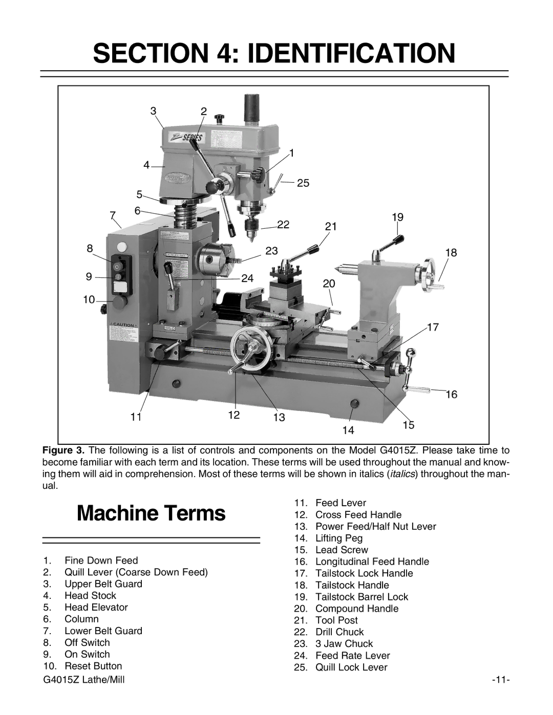
Figure 3. The following is a list of controls and components on the Model G4015Z. Please take time to become familiar with each term and its location. These terms will be used throughout the manual and know- ing them will aid in comprehension. Most of these terms will be shown in italics (italics) throughout the man- ual.
| Machine Terms | 11. | Feed Lever |
| 12. | Cross Feed Handle | |
|
| 13. | Power Feed/Half Nut Lever |
|
| 14. | Lifting Peg |
|
| ||
1. | Fine Down Feed | 15. | Lead Screw |
16. | Longitudinal Feed Handle | ||
2. | Quill Lever (Coarse Down Feed) | 17. | Tailstock Lock Handle |
3. | Upper Belt Guard | 18. | Tailstock Handle |
4. | Head Stock | 19. | Tailstock Barrel Lock |
5. | Head Elevator | 20. | Compound Handle |
6. | Column | 21. | Tool Post |
7. | Lower Belt Guard | 22. | Drill Chuck |
8. | Off Switch | 23. | 3 Jaw Chuck |
9. | On Switch | 24. | Feed Rate Lever |
10. | Reset Button | 25. | Quill Lock Lever |
G4015Z Lathe/Mill |
| ||
