Metric Threading
The metric threading gear chart is illustrated in Figure 49. The layout is listed below to help iden- tify gears for cutting threads with metric pitches. The chart below lists threads in millimeters or the theoretical amount of space one thread occupies.
| 1 |
|
|
|
| mm |
|
| 4 |
|
|
|
|
|
|
|
| ||
|
|
|
|
|
|
|
|
| |
2 | D |
|
| I |
|
|
| II |
|
A | 24 | 25 | 30 | 60 | 24 | 30 | 60 | B=120 | |
|
| ||||||||
| 24 |
|
|
| 0.4 |
| 0.4 | 0.2 |
|
| 27 |
|
|
|
|
| 0.45 |
|
|
| 30 |
|
|
| 0.5 |
|
| 0.25 |
|
| 36 | 1.5 |
|
| 0.6 | 0.75 |
| 0.3 |
|
3 | 42 | 1.75 |
|
| 0.7 |
|
| 0.35 |
|
| 60 | 2.5 |
| 2 |
| 1.25 | 1 |
|
|
| 75 |
| 3 |
|
|
|
|
|
|
Figure 49. Rates given in millimeters and inches.
Please note that charts reflect approximate apron movement per revolution.
1.The column of numbers below D represent the number of teeth on gears used in position D.
2.The numbers to the right of A represent the number of teeth on gears used in position A.
3.Field of possible thread pitches.
4.This gear will always have 120 teeth and will be intermediate to gears A and D.
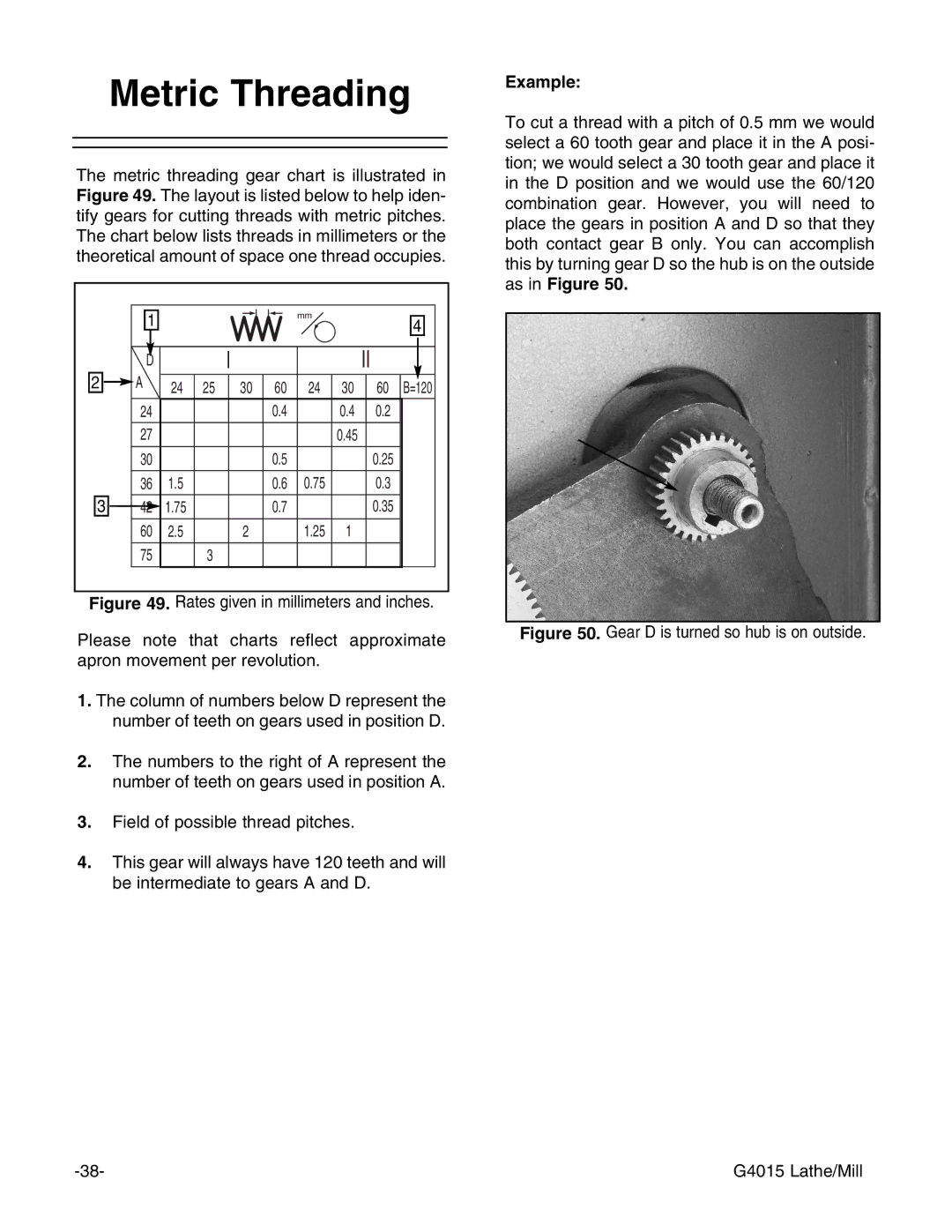
Example:
To cut a thread with a pitch of 0.5 mm we would select a 60 tooth gear and place it in the A posi- tion; we would select a 30 tooth gear and place it in the D position and we would use the 60/120 combination gear. However, you will need to place the gears in position A and D so that they both contact gear B only. You can accomplish this by turning gear D so the hub is on the outside as in Figure 50.
Figure 50. Gear D is turned so hub is on outside.
G4015 Lathe/Mill |