Inch Threading
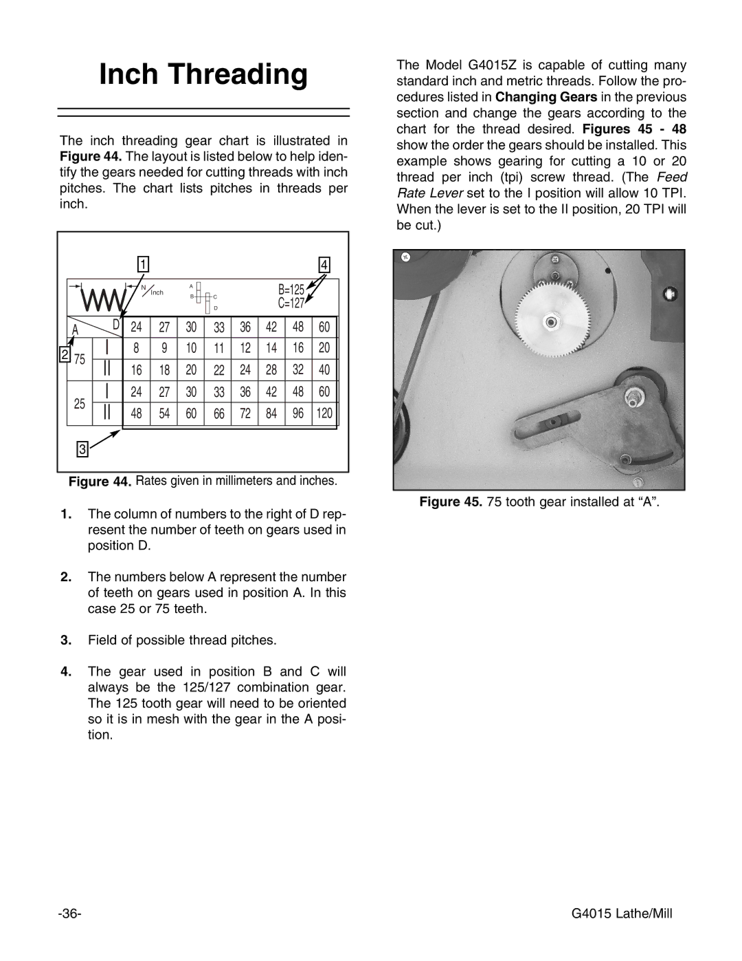
The inch threading gear chart is illustrated in Figure 44. The layout is listed below to help iden- tify the gears needed for cutting threads with inch pitches. The chart lists pitches in threads per inch.
|
| 1 |
|
|
|
|
|
| 4 |
|
| N | Inch | A |
|
|
| B=125 |
|
|
|
| B | C |
|
|
| ||
|
|
|
|
|
| C=127 |
| ||
|
|
|
|
| D |
|
|
| |
A | D | 24 | 27 | 30 | 33 | 36 | 42 | 48 | 60 |
2 75 | I | 8 | 9 | 10 | 11 | 12 | 14 | 16 | 20 |
II | 16 | 18 | 20 | 22 | 24 | 28 | 32 | 40 | |
25 | I | 24 | 27 | 30 | 33 | 36 | 42 | 48 | 60 |
II | 48 | 54 | 60 | 66 | 72 | 84 | 96 | 120 | |
3 |
|
|
|
|
|
|
|
|
|
Figure 44. Rates given in millimeters and inches.
1.The column of numbers to the right of D rep- resent the number of teeth on gears used in position D.
2.The numbers below A represent the number of teeth on gears used in position A. In this case 25 or 75 teeth.
3.Field of possible thread pitches.
4.The gear used in position B and C will always be the 125/127 combination gear. The 125 tooth gear will need to be oriented so it is in mesh with the gear in the A posi- tion.
The Model G4015Z is capable of cutting many standard inch and metric threads. Follow the pro- cedures listed in Changing Gears in the previous section and change the gears according to the chart for the thread desired. Figures 45 - 48 show the order the gears should be installed. This example shows gearing for cutting a 10 or 20 thread per inch (tpi) screw thread. (The Feed Rate Lever set to the I position will allow 10 TPI. When the lever is set to the II position, 20 TPI will be cut.)
Figure 45. 75 tooth gear installed at “A”.
G4015 Lathe/Mill |